- 您現(xiàn)在的位置:買賣IC網(wǎng) > PDF目錄224791 > PNX9520E (NXP Semiconductors N.V.) Connected media processor PDF資料下載
參數(shù)資料
| 型號: | PNX9520E |
| 廠商: | NXP Semiconductors N.V. |
| 元件分類: | 數(shù)字信號處理 |
| 英文描述: | Connected media processor |
| 封裝: | PNX9520E/N1<SOT795-1 (BGA456)|<<http://www.nxp.com/packages/SOT795-1.html<1<Always Pb-free,;PNX9520E/N1<SOT795-1 (BGA456)|<<http://www.nxp.com/packages/SOT795-1.html<1 |
| 文件頁數(shù): | 383/828頁 |
| 文件大小: | 3775K |
| 代理商: | PNX9520E |
第1頁第2頁第3頁第4頁第5頁第6頁第7頁第8頁第9頁第10頁第11頁第12頁第13頁第14頁第15頁第16頁第17頁第18頁第19頁第20頁第21頁第22頁第23頁第24頁第25頁第26頁第27頁第28頁第29頁第30頁第31頁第32頁第33頁第34頁第35頁第36頁第37頁第38頁第39頁第40頁第41頁第42頁第43頁第44頁第45頁第46頁第47頁第48頁第49頁第50頁第51頁第52頁第53頁第54頁第55頁第56頁第57頁第58頁第59頁第60頁第61頁第62頁第63頁第64頁第65頁第66頁第67頁第68頁第69頁第70頁第71頁第72頁第73頁第74頁第75頁第76頁第77頁第78頁第79頁第80頁第81頁第82頁第83頁第84頁第85頁第86頁第87頁第88頁第89頁第90頁第91頁第92頁第93頁第94頁第95頁第96頁第97頁第98頁第99頁第100頁第101頁第102頁第103頁第104頁第105頁第106頁第107頁第108頁第109頁第110頁第111頁第112頁第113頁第114頁第115頁第116頁第117頁第118頁第119頁第120頁第121頁第122頁第123頁第124頁第125頁第126頁第127頁第128頁第129頁第130頁第131頁第132頁第133頁第134頁第135頁第136頁第137頁第138頁第139頁第140頁第141頁第142頁第143頁第144頁第145頁第146頁第147頁第148頁第149頁第150頁第151頁第152頁第153頁第154頁第155頁第156頁第157頁第158頁第159頁第160頁第161頁第162頁第163頁第164頁第165頁第166頁第167頁第168頁第169頁第170頁第171頁第172頁第173頁第174頁第175頁第176頁第177頁第178頁第179頁第180頁第181頁第182頁第183頁第184頁第185頁第186頁第187頁第188頁第189頁第190頁第191頁第192頁第193頁第194頁第195頁第196頁第197頁第198頁第199頁第200頁第201頁第202頁第203頁第204頁第205頁第206頁第207頁第208頁第209頁第210頁第211頁第212頁第213頁第214頁第215頁第216頁第217頁第218頁第219頁第220頁第221頁第222頁第223頁第224頁第225頁第226頁第227頁第228頁第229頁第230頁第231頁第232頁第233頁第234頁第235頁第236頁第237頁第238頁第239頁第240頁第241頁第242頁第243頁第244頁第245頁第246頁第247頁第248頁第249頁第250頁第251頁第252頁第253頁第254頁第255頁第256頁第257頁第258頁第259頁第260頁第261頁第262頁第263頁第264頁第265頁第266頁第267頁第268頁第269頁第270頁第271頁第272頁第273頁第274頁第275頁第276頁第277頁第278頁第279頁第280頁第281頁第282頁第283頁第284頁第285頁第286頁第287頁第288頁第289頁第290頁第291頁第292頁第293頁第294頁第295頁第296頁第297頁第298頁第299頁第300頁第301頁第302頁第303頁第304頁第305頁第306頁第307頁第308頁第309頁第310頁第311頁第312頁第313頁第314頁第315頁第316頁第317頁第318頁第319頁第320頁第321頁第322頁第323頁第324頁第325頁第326頁第327頁第328頁第329頁第330頁第331頁第332頁第333頁第334頁第335頁第336頁第337頁第338頁第339頁第340頁第341頁第342頁第343頁第344頁第345頁第346頁第347頁第348頁第349頁第350頁第351頁第352頁第353頁第354頁第355頁第356頁第357頁第358頁第359頁第360頁第361頁第362頁第363頁第364頁第365頁第366頁第367頁第368頁第369頁第370頁第371頁第372頁第373頁第374頁第375頁第376頁第377頁第378頁第379頁第380頁第381頁第382頁當(dāng)前第383頁第384頁第385頁第386頁第387頁第388頁第389頁第390頁第391頁第392頁第393頁第394頁第395頁第396頁第397頁第398頁第399頁第400頁第401頁第402頁第403頁第404頁第405頁第406頁第407頁第408頁第409頁第410頁第411頁第412頁第413頁第414頁第415頁第416頁第417頁第418頁第419頁第420頁第421頁第422頁第423頁第424頁第425頁第426頁第427頁第428頁第429頁第430頁第431頁第432頁第433頁第434頁第435頁第436頁第437頁第438頁第439頁第440頁第441頁第442頁第443頁第444頁第445頁第446頁第447頁第448頁第449頁第450頁第451頁第452頁第453頁第454頁第455頁第456頁第457頁第458頁第459頁第460頁第461頁第462頁第463頁第464頁第465頁第466頁第467頁第468頁第469頁第470頁第471頁第472頁第473頁第474頁第475頁第476頁第477頁第478頁第479頁第480頁第481頁第482頁第483頁第484頁第485頁第486頁第487頁第488頁第489頁第490頁第491頁第492頁第493頁第494頁第495頁第496頁第497頁第498頁第499頁第500頁第501頁第502頁第503頁第504頁第505頁第506頁第507頁第508頁第509頁第510頁第511頁第512頁第513頁第514頁第515頁第516頁第517頁第518頁第519頁第520頁第521頁第522頁第523頁第524頁第525頁第526頁第527頁第528頁第529頁第530頁第531頁第532頁第533頁第534頁第535頁第536頁第537頁第538頁第539頁第540頁第541頁第542頁第543頁第544頁第545頁第546頁第547頁第548頁第549頁第550頁第551頁第552頁第553頁第554頁第555頁第556頁第557頁第558頁第559頁第560頁第561頁第562頁第563頁第564頁第565頁第566頁第567頁第568頁第569頁第570頁第571頁第572頁第573頁第574頁第575頁第576頁第577頁第578頁第579頁第580頁第581頁第582頁第583頁第584頁第585頁第586頁第587頁第588頁第589頁第590頁第591頁第592頁第593頁第594頁第595頁第596頁第597頁第598頁第599頁第600頁第601頁第602頁第603頁第604頁第605頁第606頁第607頁第608頁第609頁第610頁第611頁第612頁第613頁第614頁第615頁第616頁第617頁第618頁第619頁第620頁第621頁第622頁第623頁第624頁第625頁第626頁第627頁第628頁第629頁第630頁第631頁第632頁第633頁第634頁第635頁第636頁第637頁第638頁第639頁第640頁第641頁第642頁第643頁第644頁第645頁第646頁第647頁第648頁第649頁第650頁第651頁第652頁第653頁第654頁第655頁第656頁第657頁第658頁第659頁第660頁第661頁第662頁第663頁第664頁第665頁第666頁第667頁第668頁第669頁第670頁第671頁第672頁第673頁第674頁第675頁第676頁第677頁第678頁第679頁第680頁第681頁第682頁第683頁第684頁第685頁第686頁第687頁第688頁第689頁第690頁第691頁第692頁第693頁第694頁第695頁第696頁第697頁第698頁第699頁第700頁第701頁第702頁第703頁第704頁第705頁第706頁第707頁第708頁第709頁第710頁第711頁第712頁第713頁第714頁第715頁第716頁第717頁第718頁第719頁第720頁第721頁第722頁第723頁第724頁第725頁第726頁第727頁第728頁第729頁第730頁第731頁第732頁第733頁第734頁第735頁第736頁第737頁第738頁第739頁第740頁第741頁第742頁第743頁第744頁第745頁第746頁第747頁第748頁第749頁第750頁第751頁第752頁第753頁第754頁第755頁第756頁第757頁第758頁第759頁第760頁第761頁第762頁第763頁第764頁第765頁第766頁第767頁第768頁第769頁第770頁第771頁第772頁第773頁第774頁第775頁第776頁第777頁第778頁第779頁第780頁第781頁第782頁第783頁第784頁第785頁第786頁第787頁第788頁第789頁第790頁第791頁第792頁第793頁第794頁第795頁第796頁第797頁第798頁第799頁第800頁第801頁第802頁第803頁第804頁第805頁第806頁第807頁第808頁第809頁第810頁第811頁第812頁第813頁第814頁第815頁第816頁第817頁第818頁第819頁第820頁第821頁第822頁第823頁第824頁第825頁第826頁第827頁第828頁

NXP Semiconductors
PNX15xx/952x Series
Volume 1 of 1
Chapter 12: Video Input Processor
PNX15XX_PNX952X_SER_N_4
NXP B.V. 2007. All rights reserved.
Product data sheet
Rev. 4.0 — 03 December 2007
12-443
Auxiliary Data Acquisition
Capturing auxiliary data utilizes the same DMA engine used for the third video plane.
Capture of overlapping Video and Auxiliary regions is, therefore, only possible when
semi-planar or packed formats are being used. Data can be captured in either 8- or
10-bit modes. In the single-stream mode, 10-bit data is extended to 16 bits by either
adding leading zeros or by sign-extension. In dual stream mode, only 8 MSBs of a 10-
bit data are valid; two such MSB sets (2x8-bit data) are captured simultaneously, for
either 8-bit or 10-bit modes, and packed to form a resultant 16-bit unit. thus, Channel
A data (8 bits) and channel B data (8 bits) are located at the 8 LSBs and the 8 MSBs
respectively, of the packed 16-bit data.
Three different types of auxiliary data capture are dened:
Ancillary Data Capture (ANC)
Auxiliary data acquisition window (AUX)
Raw data capture (RAW)
A buffer-size register can be used to limit data acquisition by size (one shot mode) or
dene a ring-buffer length.
Even though ANC and AUX capture can be enabled separately, simultaneous capture
of ANC and AUX is not advisable. Timing and sequence of ANC and AUX data are
not necessarily related and therefore are likely to lead to unpredictable results if
simultaneous capture is attempted!
Ancillary Data Capture
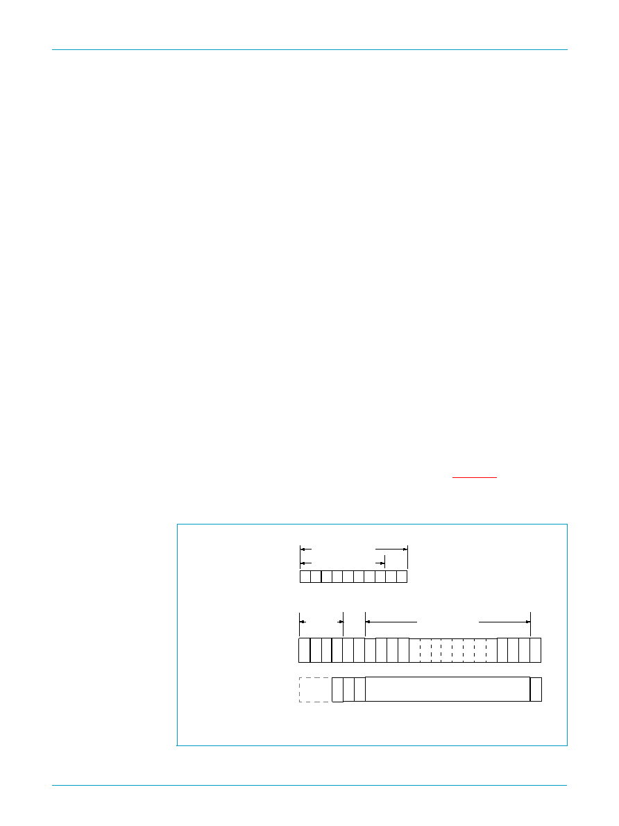
Ancillary Data, embedded in the stream and marked by ITU-R-1364 header codes,
can be decoded and extracted for software processing (see Figure 13). AUX_BPS
register species the number of bits to be captured per ANC sample. In the 8-bit
mode, two LSBs of the 10-bit data bus are ignored. Ancillary data capture is not
supported in the dual stream mode.
Figure 13: ANC Data Structure
DBN*
00
+
FF
+
FF
+
DID
DC
CS
data
ANC
preamble
user data words
(max.255)
+8 MSB of input data checked
DBN*
DC
CS
size of 8-bit user data words = DC[7:2] x 4
size of 10-bit user data words = DC[7:0]
ancillary data packet:
captured data:
data bit allocation:
3
4
1
2
0
8
9
6
7
5
8-bit data range
10-bit data range
MSB
LSB
DID
*DBN for type 1 or SDID for type 2 (ITU-R-1364)
相關(guān)PDF資料 |
PDF描述 |
|---|---|
| POE-A | CERAMIC RESONATORS |
| POE-B | CERAMIC RESONATORS |
| POS-50 | VCO, 25 MHz - 50 MHz |
| POS-ED5319/1 | VCO, 75 MHz - 114 MHz |
| PP156TWRG4-6VAC-W12 | DUAL COLOR LED, RED/GREEN, 4 mm |
相關(guān)代理商/技術(shù)參數(shù) |
參數(shù)描述 |
|---|---|
| PNX9520E/N1/S422,5 | 制造商:NXP Semiconductors 功能描述:- Tape and Reel |
| PNY CARRYING CHARGE | 制造商:PNY Technologies 功能描述:PNY CARRYING CHARGE - Virtual or Non-Physical Inventory (Software & Literature) |
| PNY-05015 | 制造商:PMI 制造商全稱:PMI 功能描述:OFF-LINE SWITCH MODE TINY SWITCH TRANSFORMERS |
| PNY-07006 | 制造商:PMI 制造商全稱:PMI 功能描述:OFF-LINE SWITCH MODE TINY SWITCH TRANSFORMERS |
| PNY-12206 | 制造商:PMI 制造商全稱:PMI 功能描述:OFF-LINE SWITCH MODE TINY SWITCH TRANSFORMERS |
發(fā)布緊急采購,3分鐘左右您將得到回復(fù)。