- 您現(xiàn)在的位置:買賣IC網(wǎng) > PDF目錄383876 > T7633 (Lineage Power) Dual T1/E1 3.3 V Short-Haul Terminator(雙T1/E1 3.3V短通信距離終端器) PDF資料下載
參數(shù)資料
| 型號(hào): | T7633 |
| 廠商: | Lineage Power |
| 英文描述: | Dual T1/E1 3.3 V Short-Haul Terminator(雙T1/E1 3.3V短通信距離終端器) |
| 中文描述: | 雙T1/E1的3.3伏短途終結(jié)者(雙T1/E1的3.3短通信距離終端器) |
| 文件頁數(shù): | 183/248頁 |
| 文件大?。?/td> | 1459K |
| 代理商: | T7633 |
第1頁第2頁第3頁第4頁第5頁第6頁第7頁第8頁第9頁第10頁第11頁第12頁第13頁第14頁第15頁第16頁第17頁第18頁第19頁第20頁第21頁第22頁第23頁第24頁第25頁第26頁第27頁第28頁第29頁第30頁第31頁第32頁第33頁第34頁第35頁第36頁第37頁第38頁第39頁第40頁第41頁第42頁第43頁第44頁第45頁第46頁第47頁第48頁第49頁第50頁第51頁第52頁第53頁第54頁第55頁第56頁第57頁第58頁第59頁第60頁第61頁第62頁第63頁第64頁第65頁第66頁第67頁第68頁第69頁第70頁第71頁第72頁第73頁第74頁第75頁第76頁第77頁第78頁第79頁第80頁第81頁第82頁第83頁第84頁第85頁第86頁第87頁第88頁第89頁第90頁第91頁第92頁第93頁第94頁第95頁第96頁第97頁第98頁第99頁第100頁第101頁第102頁第103頁第104頁第105頁第106頁第107頁第108頁第109頁第110頁第111頁第112頁第113頁第114頁第115頁第116頁第117頁第118頁第119頁第120頁第121頁第122頁第123頁第124頁第125頁第126頁第127頁第128頁第129頁第130頁第131頁第132頁第133頁第134頁第135頁第136頁第137頁第138頁第139頁第140頁第141頁第142頁第143頁第144頁第145頁第146頁第147頁第148頁第149頁第150頁第151頁第152頁第153頁第154頁第155頁第156頁第157頁第158頁第159頁第160頁第161頁第162頁第163頁第164頁第165頁第166頁第167頁第168頁第169頁第170頁第171頁第172頁第173頁第174頁第175頁第176頁第177頁第178頁第179頁第180頁第181頁第182頁當(dāng)前第183頁第184頁第185頁第186頁第187頁第188頁第189頁第190頁第191頁第192頁第193頁第194頁第195頁第196頁第197頁第198頁第199頁第200頁第201頁第202頁第203頁第204頁第205頁第206頁第207頁第208頁第209頁第210頁第211頁第212頁第213頁第214頁第215頁第216頁第217頁第218頁第219頁第220頁第221頁第222頁第223頁第224頁第225頁第226頁第227頁第228頁第229頁第230頁第231頁第232頁第233頁第234頁第235頁第236頁第237頁第238頁第239頁第240頁第241頁第242頁第243頁第244頁第245頁第246頁第247頁第248頁
Advance Data Sheet
May 1998
T7633 Dual T1/E1 3.3 V Short-Haul Terminator
173
Lucent Technologies Inc.
Framer Register Architecture
(continued)
Framer Status/Counter Registers
(continued)
Bit 0—bit 4 in this register are set high when the receive framer comes out of the unavailable state, while bit 4—bit
7 report detection of the receive test patterns.
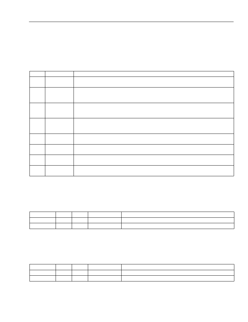
Table 96. Facility Event Register (FRM_SR7) (607; C07)
* It is possible for one of these bits to be set to 1, if the received line data is all zeros.
Bipolar Violation Counter Register (FRM_SR8—FRM_SR9)
This register contains the 16-bit count of received bipolar violations, line code violations, or excessive zeros.
Table 97. Bipolar Violation Counter Registers (FRM_SR8—FRM_SR9) ((608—609); (C08—C09))
Frame Bit Errored Counter Register (FRM_SR10—FRM_SR11)
This register contains the 16-bit count of framing bit errors. Framing bit errors are not counted during loss of frame
alignment.
Table 98. Framing Bit Error Counter Registers (FRM_SR10—FRM_SR11) ((60A—60B); (C0A—C0B))
Bit
0
Symbol
OUAS
Description
Out of Unavailable State.
A 1 indicates the receive framer detected ten consecutive
seconds that were not severely errored while in the unavailable state at the ET.
Out of Unavailable State at the ET-RE.
A 1 indicates the receive framer detected ten
consecutive seconds that were not severely errored while in the unavailable state at the
ET-RE.
Out of Unavailable State at the NT1.
A 1 indicates the receive framer detected ten
consecutive seconds that were not severely errored while in the unavailable state at the
NT.
Out of Unavailable State NT1-RE.
A 1 indicates the receive framer detected ten
consecutive seconds that were not severely errored while in the unavailable state at the
NT-RE.
Test Pattern Detected.
A 1 indicates the pattern detector has locked onto the pattern
specified by the PTRN configuration bits defined in register FRM_PR70.
Test Pattern Bit Error.
A 1 indicates the pattern detector has found one or more single
bit errors in the pattern that it is currently locked onto.
Receiving Pseudorandom Pattern.
A 1 indicates the receive framer pattern monitor
circuit is currently detecting the 2
15
– 1 pseudorandom pattern*.
Receiving Quasi-Random Pattern.
A 1 indicates the receive framer pattern monitor
circuit is currently detecting the 2
20
– 1 quasi-random pattern*.
1
EROUAS
2
NT1OUAS
3
NROUAS
4
DETECT
5
PTRNBER
6
RPSUEDO
7
RQUASI
Register
FRM_SR8
FRM_SR9
Byte
MSB
LSB
Bit
7—0
7—0
Symbol
BPV15—BPV8
BPV7—BPV0
Description
BPVs Counter.
BPVs Counter.
Register
FRM_SR10
FRM_SR11
Byte
MSB
LSB
Bit
7—0
7—0
Symbol
FBE15—FBE8
FBE7—FBE0
Description
Frame Bit Counter.
Frame Bit Errored Counter.
相關(guān)PDF資料 |
PDF描述 |
|---|---|
| T7688 | 5.0 V E1/CEPT Quad Line Interface(5.0 V E1/CEPT四線接口) |
| T7689 | 5.0 V T1 Quad Line Interface(5.0 V T1四線接口) |
| T7690 | 5.0 V T1/E1 Quad Line Interface(5.0 V T1/E1 四線接口) |
| T7693 | 3.3 V T1/E1 Quad Line Interface( 3.3 V T1/E四線接口) |
| T7698 | Quad T1/E1 Line Interface and Octal T1/E1 Monitor(四T1/E1線接口和八T1/E1監(jiān)控器) |
相關(guān)代理商/技術(shù)參數(shù) |
參數(shù)描述 |
|---|---|
| T7645036 | 功能描述:手工工具 Campbell Snap Link #2450, 7/16", Steel RoHS:否 制造商:Molex 產(chǎn)品:Extraction Tools 類型: 描述/功能:Extraction tool |
| T7645106 | 制造商:COOPER INDUSTRIES 功能描述:CC ACCESYS / #7350 1/8 Quick Link Steel Zinc Plated UPC Tagged |
| T7645126 | 制造商:COOPER INDUSTRIES 功能描述:CC ACCESYS / #7350 1/4 Quick Link Steel Zinc Plated UPC Tagged |
| T7645136V | 制造商:COOPER INDUSTRIES 功能描述:CC ACCESYS / #7350 5/16 Quick Link Steel Zinc Plated UPC Tagged |
| T7645146 | 制造商:COOPER INDUSTRIES 功能描述:CC ACCESYS / #7350 3/8 Quick Link Steel Zinc Plated UPC Tagged |
發(fā)布緊急采購,3分鐘左右您將得到回復(fù)。