- 您現(xiàn)在的位置:買賣IC網(wǎng) > PDF目錄383875 > T7234 Compliance with the New ETSI PSD Requirement PDF資料下載
參數(shù)資料
| 型號: | T7234 |
| 英文描述: | Compliance with the New ETSI PSD Requirement |
| 中文描述: | 符合新的ETSI PSD的要求 |
| 文件頁數(shù): | 89/116頁 |
| 文件大小: | 1056K |
| 代理商: | T7234 |
第1頁第2頁第3頁第4頁第5頁第6頁第7頁第8頁第9頁第10頁第11頁第12頁第13頁第14頁第15頁第16頁第17頁第18頁第19頁第20頁第21頁第22頁第23頁第24頁第25頁第26頁第27頁第28頁第29頁第30頁第31頁第32頁第33頁第34頁第35頁第36頁第37頁第38頁第39頁第40頁第41頁第42頁第43頁第44頁第45頁第46頁第47頁第48頁第49頁第50頁第51頁第52頁第53頁第54頁第55頁第56頁第57頁第58頁第59頁第60頁第61頁第62頁第63頁第64頁第65頁第66頁第67頁第68頁第69頁第70頁第71頁第72頁第73頁第74頁第75頁第76頁第77頁第78頁第79頁第80頁第81頁第82頁第83頁第84頁第85頁第86頁第87頁第88頁當(dāng)前第89頁第90頁第91頁第92頁第93頁第94頁第95頁第96頁第97頁第98頁第99頁第100頁第101頁第102頁第103頁第104頁第105頁第106頁第107頁第108頁第109頁第110頁第111頁第112頁第113頁第114頁第115頁第116頁
Data Sheet
January 1998
T7256 Single-Chip NT1 (SCNT1) Transceiver
Lucent Technologies Inc.
85
Questions and Answers
(continued)
U-Interface
(continued)
A16
: (continued)
If a transceiver can operate over Loop #1 error-
free, it should have adequate range to meet all
the other loops specified in T1.601. Loop #1 has
no bridged taps, so passing Loop #1 does not
guarantee that a transceiver will successfully
start up on every loop. Also, due to the complex
nature of 2B1Q transceiver start-up algorithms,
there may be shorter loops which could cause
start-up problems if the transceiver algorithm is
not robust. The T7256 has been tested on all of
the ANSI loops per the T1.601 standard and
passes them all successfully. Two loops com-
monly used in the lab to evaluate the perfor-
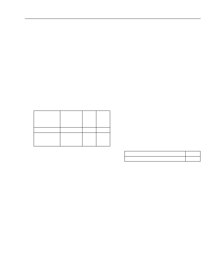
mance of the T7256 silicon are as follows:
The T7256 is able to start up and operate error-
free on both of these loops. Neither of these
loops is specified in the ANSI standard, but both
are useful for evaluation purposes. The first loop
is used because it is simple to construct and easy
to emulate using a lumped parameter cable
model, and it is very similar to ANSI Loop #1, but
the loss is slightly worse. Thus, if a transceiver
can start up on this loop and operate error-free,
its range will be adequate to meet the longest
ANSI loop. The second loop is used because,
due to its difficult bridge tap structure and its
length, it stresses the transceiver start-up algo-
rithms more than any of the ANSI-defined loops.
Therefore, if a transceiver can start up on this
loop, it should be able to meet any of the ANSI-
defined loops which have bridge taps. Also, on a
straight 26 awg loop, the T7256 can successfully
start up at lengths up to 21 kft. This fact, com-
bined with reliable start-up on the 15 kft 2BT loop
above, illustrates that the T7256 provides ample
start-up sensitivity, loop range, and robustness
on all ANSI loops. Another parameter of interest
is pulse height loss (PHL). PHL can be defined as
the loss in dB of the peak of a 2B1Q pulse rela-
tive to a 0-length loop. For an 18 kft 26 awg loop,
the PHL is about 36 dB, which is 2 dB worse than
on ANSI Loop #1. A signal-to-noise ratio (SNR)
measurement can be performed on the received
signal after all the signal processing is complete
(i.e., at the input to the slicer in the decision feed-
back equalizer). This is a measure of the ratio of
the recovered 2B1Q pulse height vs. the noise
remaining on the signal. The SNR must be
greater than 22 dB in order to operate with a bit
error rate of <1e–7. With no impairments, the
T7256 SNR is typically 32 dB on the
18 kft/26 awg loop. When all ANSI-specified
impairments are added, the SNR is about
22.7 dB, still leaving adequate margin to guaran-
tee error-free operation over all ANSI loops.
Finally, to estimate range over straight 24 awg
cable, the 18 kft loop loss can be used as a limit
(since the T7256 can operate successfully with
that amount of loss) and the following calcula-
tions can be made:
Thus, the operating range over 24 awg cable is
expected to be about 24 kft.
Q17:
What does the energy spectrum of a 2B1Q signal
look like
A17:
Figure A1 (curve P1) in the ANSI T1.601 stan-
dard illustrates what this spectrum looks like.
Loop
Configuration
Bridge
Taps (BT)
Loss
@ 20
kHz
(dB)
38.7
37.1
Loss
@ 40
kHz
(dB)
49.5
46.5
18 kft/26 awg
15 kft/26 awg
None
Two at near
end, each
3 kft/22 awg
Loss of 18 kft/26 awg loop @ 20 kHz
Loss per kft of 24 awg cable @ 20 kHz
38.7 dB
1.6 dB
38.7 dB
1.6 dB
/
kft
---------------------------
24 kft
=
相關(guān)PDF資料 |
PDF描述 |
|---|---|
| T7234A | Compliance with the New ETSI PSD Requirement |
| T7237A | Compliance with the New ETSI PSD Requirement |
| T7256A | Compliance with the New ETSI PSD Requirement |
| T7288 | CEPT/E1 Line Interface(CEPT/E1 線接口) |
| T7290A | DS1/T1/CEPT/E1 Line Interface(DS1/T1/CEPT/E1 線接口) |
相關(guān)代理商/技術(shù)參數(shù) |
參數(shù)描述 |
|---|---|
| T7234A | 制造商:AGERE 制造商全稱:AGERE 功能描述:Compliance with the New ETSI PSD Requirement |
| T7237 | 制造商:未知廠家 制造商全稱:未知廠家 功能描述:Compliance with the New ETSI PSD Requirement |
| T7237A | 制造商:AGERE 制造商全稱:AGERE 功能描述:Compliance with the New ETSI PSD Requirement |
| T7240 | 制造商:TE Connectivity 功能描述: |
| T7-241A5 | 功能描述:撥動開關(guān) ON NONE OFF 2 Pole Standard Bat Handle RoHS:否 制造商:OTTO 觸點(diǎn)形式: 開關(guān)功能: 電流額定值: 電壓額定值 AC: 電壓額定值 DC: 功率額定值: 端接類型: 安裝風(fēng)格: 端子密封: 觸點(diǎn)電鍍: 照明: |
發(fā)布緊急采購,3分鐘左右您將得到回復(fù)。