- 您現(xiàn)在的位置:買賣IC網(wǎng) > PDF目錄383875 > T7234 Compliance with the New ETSI PSD Requirement PDF資料下載
參數(shù)資料
| 型號: | T7234 |
| 英文描述: | Compliance with the New ETSI PSD Requirement |
| 中文描述: | 符合新的ETSI PSD的要求 |
| 文件頁數(shù): | 105/116頁 |
| 文件大小: | 1056K |
| 代理商: | T7234 |
第1頁第2頁第3頁第4頁第5頁第6頁第7頁第8頁第9頁第10頁第11頁第12頁第13頁第14頁第15頁第16頁第17頁第18頁第19頁第20頁第21頁第22頁第23頁第24頁第25頁第26頁第27頁第28頁第29頁第30頁第31頁第32頁第33頁第34頁第35頁第36頁第37頁第38頁第39頁第40頁第41頁第42頁第43頁第44頁第45頁第46頁第47頁第48頁第49頁第50頁第51頁第52頁第53頁第54頁第55頁第56頁第57頁第58頁第59頁第60頁第61頁第62頁第63頁第64頁第65頁第66頁第67頁第68頁第69頁第70頁第71頁第72頁第73頁第74頁第75頁第76頁第77頁第78頁第79頁第80頁第81頁第82頁第83頁第84頁第85頁第86頁第87頁第88頁第89頁第90頁第91頁第92頁第93頁第94頁第95頁第96頁第97頁第98頁第99頁第100頁第101頁第102頁第103頁第104頁當(dāng)前第105頁第106頁第107頁第108頁第109頁第110頁第111頁第112頁第113頁第114頁第115頁第116頁
Data Sheet
January 1998
T7256 Single-Chip NT1 (SCNT1) Transceiver
Lucent Technologies Inc.
101
Questions and Answers
(continued)
Miscellaneous
(continued)
Q53:
Can you provide detailed information on the
active and idle power consumption of the T7256
A53:
The IDLE power of the T7256 is typically 35 mW.
The IDLE power will be increased if CKOUT or
the TDM highway are active. The discussion
below presents accurate numbers for adding in
the effects of CKOUT and the TDM highway.
When considering active power measurement fig-
ures, it is important to note that the conditions
under which power measurements are made are
not always completely stated by 2B1Q IC ven-
dors. For example, loop length is not typically
mentioned in the context of power dissipation, yet
power dissipation on a short loop is noticeably
greater than on a long loop. There are two rea-
sons for the increased power dissipation at
shorter loop lengths:
1. The overall loop impedance is smaller, requir-
ing a higher current to drive the loop.
2. The far-end transceiver is closer, requiring the
near-end transceiver to sink more far-end cur-
rent in order to maintain a virtual ground at its
transmitter outputs.
The following lab measurements provide an
example of how power dissipation varies with
loop length for a specific T7256 with its
15.36 MHz CKOUT output disabled (see the fol-
lowing table for information on CKOUT). Note that
power dissipation on a 0-length loop (the worst-
case loop) is about 35 mW higher than on a loop
of >3 kft length—a significant difference. Thus,
loop length needs to be considered when deter-
mining worst-case power numbers.
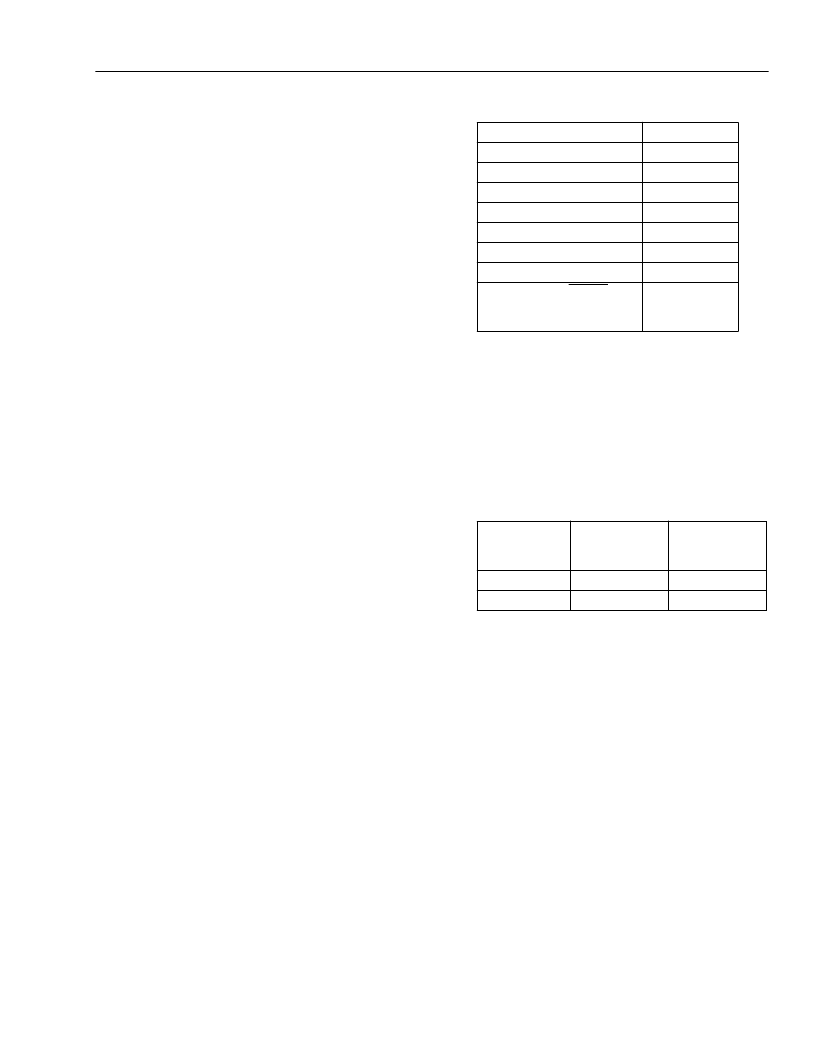
Table 43. Power Dissipation Variation
* This is the configuration used by some IC manufacturers.
Also, in the case of the T7256, the use of the out-
put clock CKOUT (pin 17) needs to be considered
since its influence on power dissipation is signifi-
cant. Some applications may make use of this
clock, while others may leave it 3-stated. The
power dissipation of CKOUT is shown in Table
44.
Table 44. Power Dissipation of CKOUT
Another factor influencing power consumption is
the S/T-interface data pattern. For example, when
transmitting an INFO 4 pattern with all 1s data in
the B and D channels, the power consumption is
25 mW lower than it is when transmitting INFO 2,
because INFO 2 is worst case in terms of the
amount of +0 and –0 transitions, and INFO 4 is
best case if the data is all 1s. A typical number
would lie about midway between these two. The
T7256 TDM highway, when active, can add
another 3 mW of power.
Loop Configuration
18 kft/26 awg
6 kft/26 awg
3 kft/26 awg
2 kft/26 awg
1 kft/26 awg
0.5 kft/26 awg
0 kft
135
load, ILOSS or
LPBK active, no far-end
transceiver*
Power (mW)
270
270
274
277
285
293
305
278
CKOUT
Frequency
(MHz)
15.36
10.24
Power Due to
CKOUT 40 pF
Load (mW)
21.3
17.7
Power Due to
CKOUT No
Load (mW)
11.0
9.1
相關(guān)PDF資料 |
PDF描述 |
|---|---|
| T7234A | Compliance with the New ETSI PSD Requirement |
| T7237A | Compliance with the New ETSI PSD Requirement |
| T7256A | Compliance with the New ETSI PSD Requirement |
| T7288 | CEPT/E1 Line Interface(CEPT/E1 線接口) |
| T7290A | DS1/T1/CEPT/E1 Line Interface(DS1/T1/CEPT/E1 線接口) |
相關(guān)代理商/技術(shù)參數(shù) |
參數(shù)描述 |
|---|---|
| T7234A | 制造商:AGERE 制造商全稱:AGERE 功能描述:Compliance with the New ETSI PSD Requirement |
| T7237 | 制造商:未知廠家 制造商全稱:未知廠家 功能描述:Compliance with the New ETSI PSD Requirement |
| T7237A | 制造商:AGERE 制造商全稱:AGERE 功能描述:Compliance with the New ETSI PSD Requirement |
| T7240 | 制造商:TE Connectivity 功能描述: |
| T7-241A5 | 功能描述:撥動開關(guān) ON NONE OFF 2 Pole Standard Bat Handle RoHS:否 制造商:OTTO 觸點形式: 開關(guān)功能: 電流額定值: 電壓額定值 AC: 電壓額定值 DC: 功率額定值: 端接類型: 安裝風(fēng)格: 端子密封: 觸點電鍍: 照明: |
發(fā)布緊急采購,3分鐘左右您將得到回復(fù)。