- 您現(xiàn)在的位置:買賣IC網 > PDF目錄384024 > TMX320DM6446ZWT (Texas Instruments, Inc.) Digital Media System on-Chip PDF資料下載
參數資料
| 型號: | TMX320DM6446ZWT |
| 廠商: | Texas Instruments, Inc. |
| 英文描述: | Digital Media System on-Chip |
| 中文描述: | 數字媒體系統(tǒng)芯片 |
| 文件頁數: | 152/214頁 |
| 文件大?。?/td> | 1699K |
| 代理商: | TMX320DM6446ZWT |
第1頁第2頁第3頁第4頁第5頁第6頁第7頁第8頁第9頁第10頁第11頁第12頁第13頁第14頁第15頁第16頁第17頁第18頁第19頁第20頁第21頁第22頁第23頁第24頁第25頁第26頁第27頁第28頁第29頁第30頁第31頁第32頁第33頁第34頁第35頁第36頁第37頁第38頁第39頁第40頁第41頁第42頁第43頁第44頁第45頁第46頁第47頁第48頁第49頁第50頁第51頁第52頁第53頁第54頁第55頁第56頁第57頁第58頁第59頁第60頁第61頁第62頁第63頁第64頁第65頁第66頁第67頁第68頁第69頁第70頁第71頁第72頁第73頁第74頁第75頁第76頁第77頁第78頁第79頁第80頁第81頁第82頁第83頁第84頁第85頁第86頁第87頁第88頁第89頁第90頁第91頁第92頁第93頁第94頁第95頁第96頁第97頁第98頁第99頁第100頁第101頁第102頁第103頁第104頁第105頁第106頁第107頁第108頁第109頁第110頁第111頁第112頁第113頁第114頁第115頁第116頁第117頁第118頁第119頁第120頁第121頁第122頁第123頁第124頁第125頁第126頁第127頁第128頁第129頁第130頁第131頁第132頁第133頁第134頁第135頁第136頁第137頁第138頁第139頁第140頁第141頁第142頁第143頁第144頁第145頁第146頁第147頁第148頁第149頁第150頁第151頁當前第152頁第153頁第154頁第155頁第156頁第157頁第158頁第159頁第160頁第161頁第162頁第163頁第164頁第165頁第166頁第167頁第168頁第169頁第170頁第171頁第172頁第173頁第174頁第175頁第176頁第177頁第178頁第179頁第180頁第181頁第182頁第183頁第184頁第185頁第186頁第187頁第188頁第189頁第190頁第191頁第192頁第193頁第194頁第195頁第196頁第197頁第198頁第199頁第200頁第201頁第202頁第203頁第204頁第205頁第206頁第207頁第208頁第209頁第210頁第211頁第212頁第213頁第214頁
www.ti.com
P
TMS320DM6446
Digital Media System on-Chip
SPRS283–DECEMBER 2005
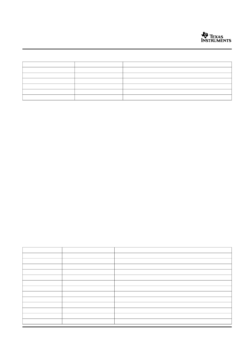
Table 5-42. VPFE Register Descriptions
HEX ADDRESS RANGE
0x01C7 0400 – 0x01C7 07FF
0x01C7 0800 – 0x01C7 0BFF
0x01C7 0C00 – 0x01C7 09FF
0x01C7 1000 – 0x01C7 13FF
0x01C7 1400 – 0x01C7 17FF
0x01C7 3400 – 0x01C7 3FFF
ACRONYM
CCDC
PREV
RESZ
HIST
H3A
VPSS
REGISTER NAME
VPFE – CCD Controller
VPFE – Preview Engine/Image Signal Processor
VPFE – Resizer
VPFE – Histogram
VPFE – Hardware 3A (Auto-Focus/WB/Exposure)
VPSS Shared Buffer Logic Registers
5.13.1.1
CCD Controller (CCDC)
The CCDC receives raw image/video data from sensors (CMOS or CCD) or YUV video data in numerous
formats from video decoder devices. The following features are supported by the CCDC module.
Conventional Bayer pattern formats.
Generates HD/VD timing signals and field ID to an external timing generator or can synchronize to an
external timing generator.
Interface to progressive and interlaced sensors.
Up to 75 MHz sensor clock in the normal mode of operation (1.05v).
REC656/CCIR-656 standard (YCbCr 422 format, either 8- or 16-bit).
YCbCr 422 format, either 8- or 16-bit with discrete H and VSYNC signals.
Up to 16-bit input.
Optical black clamping signal generation.
Shutter signal control.
Digital clamping and black level compensation.
10-bit to 8-bit A-law compression.
Low-pass filter prior to writing to SDRAM. If this filter is enabled, 2 pixels each in the left and right
edges of each line are cropped from the output.
Output range from 16-bits to 8-bits wide (8-bits wide allows for 50% saving in storage area).
Downsampling via programmable culling patterns.
Control output to the DDR2 via an external write enable signal.
Up to 16K pixels (image size) in both the horizontal and vertical direction.
The CCDC register memory mapping is shown in
Table 5-43
.
Table 5-43. CCDC Register Descriptions
HEX ADDRESS RANGE
0x01C7 0400
0x01C7 0404
0x01C7 0408
0x01C7 040C
0x01C7 0410
0x01C7 0414
0x01C7 0418
0x01C7 041C
0x01C7 0420
0x01C7 0424
0x01C7 0428
0x01C7 042C
0x01C7 0430
REGISTER ACRONYM
DESCRIPTION
PID
PCR
SYN_MODE
HD_VD_WID
PIX_LINES
HORZ_INFO
VERT_START
VERT_LINES
CULLING
HSIZE_OFF
SDOFST
SDR_ADDR
CLAMP
Peripheral Revision and Class Information
Peripheral Control Register
SYNC and Mode Set Register
HD and VD Signal Width
Number of Pixels in a Horizontal Line and Number of Lines in a Frame
Horizontal Pixel Information
Vertical Line - Settings for the Starting Pixel
Number of Vertical Lines
Culling Information in Horizontal and Vertical Directions
Horizontal Size
SDRAM/DDRAM Line Offset
SDRAM Address
Optical Black Clamping Settings
152
Peripheral and Electrical Specifications
相關PDF資料 |
PDF描述 |
|---|---|
| TN28F010-90 | 28F010 1024K (128K X 8) CMOS FLASH MEMORY |
| TN28F010-120 | 28F010 1024K (128K X 8) CMOS FLASH MEMORY |
| TN28F010-150 | 28F010 1024K (128K X 8) CMOS FLASH MEMORY |
| TN28F020-90 | 28F020 2048K (256K X 8) CMOS FLASH MEMORY |
| TN28F020-150 | 28F020 2048K (256K X 8) CMOS FLASH MEMORY |
相關代理商/技術參數 |
參數描述 |
|---|---|
| TMX320DM6467TZUT1 | 制造商:Texas Instruments 功能描述: |
| TMX320DM6467ZUT | 功能描述:數字信號處理器和控制器 - DSP, DSC Dig Media System-on- Chip RoHS:否 制造商:Microchip Technology 核心:dsPIC 數據總線寬度:16 bit 程序存儲器大小:16 KB 數據 RAM 大小:2 KB 最大時鐘頻率:40 MHz 可編程輸入/輸出端數量:35 定時器數量:3 設備每秒兆指令數:50 MIPs 工作電源電壓:3.3 V 最大工作溫度:+ 85 C 封裝 / 箱體:TQFP-44 安裝風格:SMD/SMT |
| TMX320DM647ZUT720 | 制造商:TI 制造商全稱:Texas Instruments 功能描述:Digital Media Processor |
| TMX320DM647ZUT900 | 制造商:TI 制造商全稱:Texas Instruments 功能描述:Digital Media Processor |
| TMX320DM648ACUT7 | 制造商:Texas Instruments 功能描述:- Trays |
發(fā)布緊急采購,3分鐘左右您將得到回復。