- 您現(xiàn)在的位置:買賣IC網 > PDF目錄1916 > DS34S132GN+ (Maxim Integrated Products)IC TDM OVER PACKET 676-BGA PDF資料下載
參數(shù)資料
| 型號: | DS34S132GN+ |
| 廠商: | Maxim Integrated Products |
| 文件頁數(shù): | 134/194頁 |
| 文件大?。?/td> | 0K |
| 描述: | IC TDM OVER PACKET 676-BGA |
| 產品培訓模塊: | Lead (SnPb) Finish for COTS Obsolescence Mitigation Program |
| 標準包裝: | 40 |
| 功能: | TDM-over-Packet(TDMoP) |
| 接口: | TDMoP |
| 電路數(shù): | 1 |
| 電源電壓: | 1.8V, 3.3V |
| 工作溫度: | -40°C ~ 85°C |
| 安裝類型: | 表面貼裝 |
| 封裝/外殼: | 676-BGA |
| 供應商設備封裝: | 676-PBGA(27x27) |
| 包裝: | 管件 |
| 其它名稱: | 90-34S13+2N0 |
第1頁第2頁第3頁第4頁第5頁第6頁第7頁第8頁第9頁第10頁第11頁第12頁第13頁第14頁第15頁第16頁第17頁第18頁第19頁第20頁第21頁第22頁第23頁第24頁第25頁第26頁第27頁第28頁第29頁第30頁第31頁第32頁第33頁第34頁第35頁第36頁第37頁第38頁第39頁第40頁第41頁第42頁第43頁第44頁第45頁第46頁第47頁第48頁第49頁第50頁第51頁第52頁第53頁第54頁第55頁第56頁第57頁第58頁第59頁第60頁第61頁第62頁第63頁第64頁第65頁第66頁第67頁第68頁第69頁第70頁第71頁第72頁第73頁第74頁第75頁第76頁第77頁第78頁第79頁第80頁第81頁第82頁第83頁第84頁第85頁第86頁第87頁第88頁第89頁第90頁第91頁第92頁第93頁第94頁第95頁第96頁第97頁第98頁第99頁第100頁第101頁第102頁第103頁第104頁第105頁第106頁第107頁第108頁第109頁第110頁第111頁第112頁第113頁第114頁第115頁第116頁第117頁第118頁第119頁第120頁第121頁第122頁第123頁第124頁第125頁第126頁第127頁第128頁第129頁第130頁第131頁第132頁第133頁當前第134頁第135頁第136頁第137頁第138頁第139頁第140頁第141頁第142頁第143頁第144頁第145頁第146頁第147頁第148頁第149頁第150頁第151頁第152頁第153頁第154頁第155頁第156頁第157頁第158頁第159頁第160頁第161頁第162頁第163頁第164頁第165頁第166頁第167頁第168頁第169頁第170頁第171頁第172頁第173頁第174頁第175頁第176頁第177頁第178頁第179頁第180頁第181頁第182頁第183頁第184頁第185頁第186頁第187頁第188頁第189頁第190頁第191頁第192頁第193頁第194頁

DS34S132 DATA SHEET
19-4750; Rev 1; 07/11
44 of 194
Each HDLC Engine can be programmed to use MSbit or LSbit first transmission (BCDR1.SCSNRE). This function
does not specify which bits of the Timeslot are used (previous paragraphs), but instead specifies whether the MSbit
or LSbit of each HDLC coded byte is transmitted first (the byte order is always MSByte first). For example, if LSbit
transmission and 8-bit coding are selected, then the LSbit of each byte is transmitted first (in the “bit 8” position of
the Timeslot). If instead MSbit transmission and 8-bit coding are selected then the MSbit of each byte is transmitted
first (in “bit 8”). Most T1/E1 applications use MSbit first.
Each HDLC Bundle can be programmed to include a 16-bit, 32-bit or “no” FCS (B.BCDR1SCRXBCSS and
SCTXBCSS).
In the TXP direction the HDLC Engine receives data from a TDM Port and removes the HDLC encoding (HDLC
Flags and HDLC Control Characters). The de-encoded packet data is buffered until a complete packet has been
received. After the HDLC FCS has been verified to be correct, the packet is queued for transmission as the payload
of a TXP HDLC Bundle packet.
TXP HDLC Bundles can optionally include RTP and Control Word Headers (enabled using the TXP Header
Descriptor). For RTP and/or Control Word headers can use Sequence Numbers that are always “zero”, or are
constantly incremented by one with each successive packet (B.BCDR4.SCTXCE and B.BCDR1.SCTXDFSE).
When incremented Sequence Numbers are used the S132 can be programmed to skip or include the Sequence
Number = “zero” value when the Sequence Number reaches roll-over.
In the RXP direction, when the RXP Classifier identifies an error-free packet for an HDLC Bundle, the PW packet
header and FCS are removed and the PW packet payload is stored for later processing by the RXP HDLC Engine.
The HDLC Engine inserts a Flag (Packet Delimiter = 0x7E) in between each successive RXP Packet to identify the
start and stop of each packet. The G.GCR.RXHMFIS register specifies the minimum number of Flags that are
inserted in between 2 HDLC packets where RXHMFIS + 1 = minimum number of flags (e.g. RXHMFIS = 0 for 1
flag). When the HDLC Engine no longer has a packet to forward and the minimum number of flags have been
transmitted the HDLC engine inserts “Inter-frame Fill” into the outgoing HDLC data stream. The Inter-frame Fill
value can be programmed to 0x7E or 0xFF (B.BCDR4.SCLVI).
In the RXP direction the S132 does not provide re-ordering of mis-ordered HDLC packets, so the optional RTP
and/or Control Word Sequence Numbers received in packets for RXP HDLC Bundles are ignored.
The B.BCDR1.PMS register is used to define the largest Ethernet packet that is accepted for an RXP HDLC
Bundle. Packets with a size greater than PMS are discarded.
Special Considerations
The S132 does not provide special handling for CAS Signaling when a T1/E1 Port includes an RXP HDLC Bundle.
If CAS Signaling is enabled for the T1/E1 Port and if the “overwrite CAS on TDAT” is enabled, CAS values will be
written in Timeslot positions assigned to HDLC Bundles. To prevent this, the HDLC 7-bit Sampling format can be
used, or else TSIG can be used to provide the CAS values (disable the “Overwrite CAS on TDAT”). In the TXP
direction, the RSIG value and the SW TXP CAS functions are ignored by TXP HDLC Bundles.
9.2.5.1.1 SAT/CES Engine
The S132 includes 256 SAT/CES Engines, one for each of the 256 possible SAT/CES Bundles.
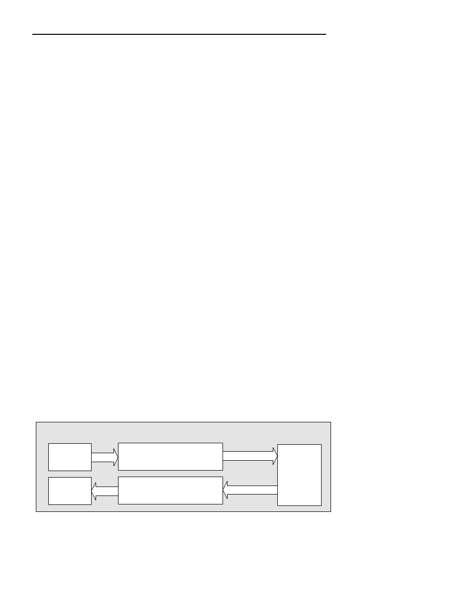
Figure 9-15. SAT/CES Engine Environment
DS34S132
TXP
TSA
RXP
TSA
TXP SAT/CES Engine
RXP SAT/CES Engine
Buffer
Manager
TDM
Connection
In the RXP direction, B.BCDR1.PMS specifies the expected packet payload size for each RXP Bundle (not
including the optional CAS bytes). For SAT applications, PMS specifies how many bytes; for CES applications, how
many frames. In the TXP direction, the PMS setting determines the amount of data that is included in the payload
of each TXP Bundle packet.
相關PDF資料 |
PDF描述 |
|---|---|
| DS34T102GN+ | IC TDM OVER PACKET 484TEBGA |
| DS3501U+H | IC POT NV 128POS HV 10-USOP |
| DS3502U+ | IC POT DGTL NV 128TAP 10-MSOP |
| DS3503U+ | IC POT DGTL NV 128TAP 10-MSOP |
| DS3897MX | IC TXRX BTL TRAPEZIODAL 20-SOIC |
相關代理商/技術參數(shù) |
參數(shù)描述 |
|---|---|
| DS34S132GN+ | 功能描述:通信集成電路 - 若干 32Port TDM-Over-Pack Transport Device RoHS:否 制造商:Maxim Integrated 類型:Transport Devices 封裝 / 箱體:TECSBGA-256 數(shù)據速率:100 Mbps 電源電壓-最大:1.89 V, 3.465 V 電源電壓-最小:1.71 V, 3.135 V 電源電流:50 mA, 225 mA 最大工作溫度:+ 85 C 最小工作溫度:- 40 C 封裝:Tube |
| DS34S132GNA2+ | 功能描述:通信集成電路 - 若干 32Port TDM-Over-Pack Transport Device RoHS:否 制造商:Maxim Integrated 類型:Transport Devices 封裝 / 箱體:TECSBGA-256 數(shù)據速率:100 Mbps 電源電壓-最大:1.89 V, 3.465 V 電源電壓-最小:1.71 V, 3.135 V 電源電流:50 mA, 225 mA 最大工作溫度:+ 85 C 最小工作溫度:- 40 C 封裝:Tube |
| DS34T101 | 制造商:MAXIM 制造商全稱:Maxim Integrated Products 功能描述:Single/Dual/Quad/Octal TDM-over-Packet Chip |
| DS34T101_08 | 制造商:MAXIM 制造商全稱:Maxim Integrated Products 功能描述:Single/Dual/Quad/Octal TDM-over-Packet Chip |
| DS34T101_09 | 制造商:MAXIM 制造商全稱:Maxim Integrated Products 功能描述:Single/Dual/Quad/Octal TDM-over-Packet Chip |
發(fā)布緊急采購,3分鐘左右您將得到回復。