- 您現(xiàn)在的位置:買賣IC網(wǎng) > PDF目錄384032 > TVP3026-220 (Texas Instruments, Inc.) Video Interface PALETTE Exract(組合像素模式視頻接口調(diào)色器) PDF資料下載
參數(shù)資料
| 型號: | TVP3026-220 |
| 廠商: | Texas Instruments, Inc. |
| 英文描述: | Video Interface PALETTE Exract(組合像素模式視頻接口調(diào)色器) |
| 中文描述: | 視頻接口調(diào)色板Exract(組合像素模式視頻接口調(diào)色器) |
| 文件頁數(shù): | 17/107頁 |
| 文件大?。?/td> | 707K |
| 代理商: | TVP3026-220 |
第1頁第2頁第3頁第4頁第5頁第6頁第7頁第8頁第9頁第10頁第11頁第12頁第13頁第14頁第15頁第16頁當前第17頁第18頁第19頁第20頁第21頁第22頁第23頁第24頁第25頁第26頁第27頁第28頁第29頁第30頁第31頁第32頁第33頁第34頁第35頁第36頁第37頁第38頁第39頁第40頁第41頁第42頁第43頁第44頁第45頁第46頁第47頁第48頁第49頁第50頁第51頁第52頁第53頁第54頁第55頁第56頁第57頁第58頁第59頁第60頁第61頁第62頁第63頁第64頁第65頁第66頁第67頁第68頁第69頁第70頁第71頁第72頁第73頁第74頁第75頁第76頁第77頁第78頁第79頁第80頁第81頁第82頁第83頁第84頁第85頁第86頁第87頁第88頁第89頁第90頁第91頁第92頁第93頁第94頁第95頁第96頁第97頁第98頁第99頁第100頁第101頁第102頁第103頁第104頁第105頁第106頁第107頁
2–3
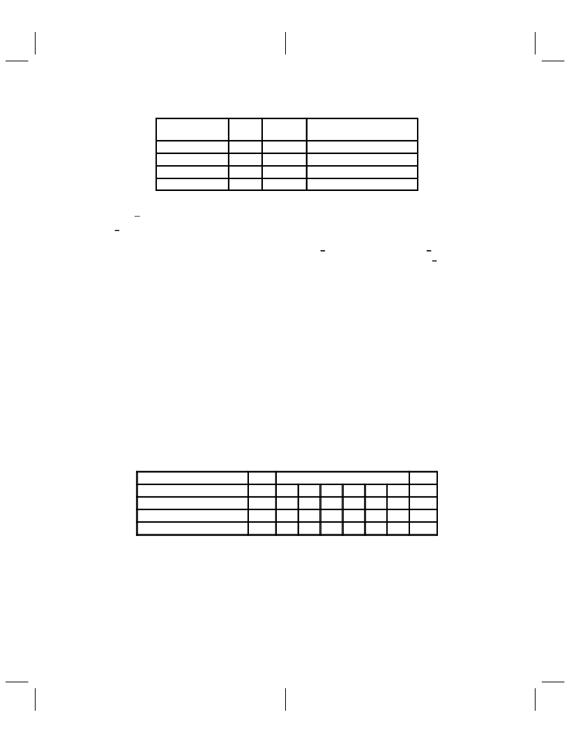
Table 2–2. Indirect Register Map (Extended Registers) (Continued)
INDEX
R/W
DEFAULT
REGISTER ADDRESSED
BY INDEX REGISTER
0x3D
R
XX
CRC Remainder MSB
0x3E
W
XX
CRC Bit Select
0x3F
R
0x26
ID
0xFF
W
XX
Software Reset
NOTE 1: Reserved registers should be avoided; otherwise, circuit behavior
could deviate from that specified.
2.1.1
The 8/6 terminal is used to select between an 8-bit (set to 1) or 6-bit (reset to 0) data path to the color palette
RAM and it is provided in order to maintain compatibility with the INMOS IMSG176. When
miscellaneous-control register bit 2 (MSC2) is set to 1, the 8/6 terminal is disabled and 8/6 operation is
controlled by bit 3 of the miscellaneous-control register (MSC3). The reset default is for the 8/6 terminal to
be enabled (miscellaneous-control register bit 2 = 0, see Section 2.2, Color Palette RAM).
8/6 Operation
2.1.2
The pixel read-mask register (direct register: 0010) is an 8-bit register used to enable or disable a bit plane
from addressing the color-palette RAM in the pseudo-color and VGA modes. Each palette address bit is
logically ANDed with the corresponding bit from the read-mask register before going to the palette-page
register and addressing the palette RAM.
Pixel Read-Mask Register
2.1.3
The palette page register (index: 0x1C) allows selection of multiple color look-up tables stored in the palette
RAM when using a mode that addresses the palette RAM with less than 8 bits. When using 1, 2, or 4 bit
planes in the pseudo-color or direct-color + overlay modes, the additional planes are provided from the page
register before the data addresses the color palette. This is illustrated in Table 2–3.
Palette-Page Register
NOTE
The additional bits from the page register are inserted after the read mask.
The palette-page register specifies the additional bit planes for the overlay field in
direct-color modes with less than 8 bits per pixel overlay.
Table 2–3. Allocation of Palette-Page Register Bits
NUMBER OF BIT PLANES
MSB
PALETTE ADDRESS BITS
LSB
8
M
M
M
M
M
M
M
M
4
P7
P6
P5
P4
M
M
M
M
2
P7
P6
P5
P4
P3
P2
M
M
1
P7
P6
P5
P4
P3
P2
P1
M
M = bit from pixel port and Pn = n bit from page register.
相關(guān)PDF資料 |
PDF描述 |
|---|---|
| TVP3026-250 | Video Interface PALETTE Exract(組合像素模式視頻接口調(diào)色器) |
| TX24 | 60.8 MM 5 X 8 DOT MATRIX DISPLAYS |
| TXB0102DCTR | 2-BIT BIDIRECTIONAL VOLTAGE-LEVEL TRANSLATOR WITH AUTO DIRECTION SENSING AND 【15-kV ESD PROTECTION |
| TXB0102DCTT | 2-BIT BIDIRECTIONAL VOLTAGE-LEVEL TRANSLATOR WITH AUTO DIRECTION SENSING AND 【15-kV ESD PROTECTION |
| TZX7V5D | surface mount silicon Zener diodes |
相關(guān)代理商/技術(shù)參數(shù) |
參數(shù)描述 |
|---|---|
| TVP3026-220AMDN | 制造商:TI 制造商全稱:Texas Instruments 功能描述:Video Interface Palette |
| TVP3026-220APCE | 制造商:TI 制造商全稱:Texas Instruments 功能描述:Video Interface Palette |
| TVP3026-220BMDN | 制造商:TI 制造商全稱:Texas Instruments 功能描述:Video Interface Palette |
| TVP3026-220BPCE | 制造商:Rochester Electronics LLC 功能描述:- Bulk |
| TVP3026-220MDN | 制造商:未知廠家 制造商全稱:未知廠家 功能描述:Video DAC with Color Palette (RAMDAC) |
發(fā)布緊急采購,3分鐘左右您將得到回復。