- 您現(xiàn)在的位置:買賣IC網(wǎng) > PDF目錄1962 > PI7C9X7954AFDE (Pericom)IC PCIE-TO-UART BRIDGE 128LQFP PDF資料下載
參數(shù)資料
| 型號(hào): | PI7C9X7954AFDE |
| 廠商: | Pericom |
| 文件頁(yè)數(shù): | 60/70頁(yè) |
| 文件大小: | 0K |
| 描述: | IC PCIE-TO-UART BRIDGE 128LQFP |
| 標(biāo)準(zhǔn)包裝: | 90 |
| 應(yīng)用: | PCIe至UART橋接 |
| 接口: | 高級(jí)配置電源接口(ACPI) |
| 電源電壓: | 1.8V, 3.3V |
| 封裝/外殼: | 128-LQFP 裸露焊盤 |
| 供應(yīng)商設(shè)備封裝: | 128-LQFP(14x14) |
| 包裝: | 托盤 |
| 安裝類型: | 表面貼裝 |
第1頁(yè)第2頁(yè)第3頁(yè)第4頁(yè)第5頁(yè)第6頁(yè)第7頁(yè)第8頁(yè)第9頁(yè)第10頁(yè)第11頁(yè)第12頁(yè)第13頁(yè)第14頁(yè)第15頁(yè)第16頁(yè)第17頁(yè)第18頁(yè)第19頁(yè)第20頁(yè)第21頁(yè)第22頁(yè)第23頁(yè)第24頁(yè)第25頁(yè)第26頁(yè)第27頁(yè)第28頁(yè)第29頁(yè)第30頁(yè)第31頁(yè)第32頁(yè)第33頁(yè)第34頁(yè)第35頁(yè)第36頁(yè)第37頁(yè)第38頁(yè)第39頁(yè)第40頁(yè)第41頁(yè)第42頁(yè)第43頁(yè)第44頁(yè)第45頁(yè)第46頁(yè)第47頁(yè)第48頁(yè)第49頁(yè)第50頁(yè)第51頁(yè)第52頁(yè)第53頁(yè)第54頁(yè)第55頁(yè)第56頁(yè)第57頁(yè)第58頁(yè)第59頁(yè)當(dāng)前第60頁(yè)第61頁(yè)第62頁(yè)第63頁(yè)第64頁(yè)第65頁(yè)第66頁(yè)第67頁(yè)第68頁(yè)第69頁(yè)第70頁(yè)
PI7C9X7954
PCI Express Quad UART
Datasheet
Page 63 of 70
May 2013 – Revision 1.4
Pericom Semiconductor
8. EEPROM INTERFACE
The EEPROM interface consists of five pins: SR_DI (EEPROM data input), SR_DO (EEPROM data
output), SR_CS (EEPROM chip select), SR_CLK_O (EEPROM clock output), and SR_ORG (EEPROM
organization). The device may control a 93C56 or compatible parts using 2K bits. The EEPROM is used to
initialize a number of registers before enumeration. This is accomplished at start-up when RTS[0] is
de-asserted, at which time the data from the EEPROM is loaded. The EEPROM interface is organized into
a 16-bit base, and the device supplies a 7-bit EEPROM word address.
8.1. AUTO MODE EERPOM ACCESS
The device may access the EEPROM in a WORD or BYTE format, which is decided by the SR_ORG# at
start-up. If SR_ORG# is asserted at start-up, EEPROM is accessed using the WORD format. Otherwise,
Byte format is used.
8.2. EEPROM MODE AT RESET
During a reset, the device will automatically load the information/data from the EEPROM if the automatic
load condition is met. The first offset in the EEPROM contains a signature. If the signature is recognized,
and if RTS[0] is de-asserted, the autoload initiates right after the reset.
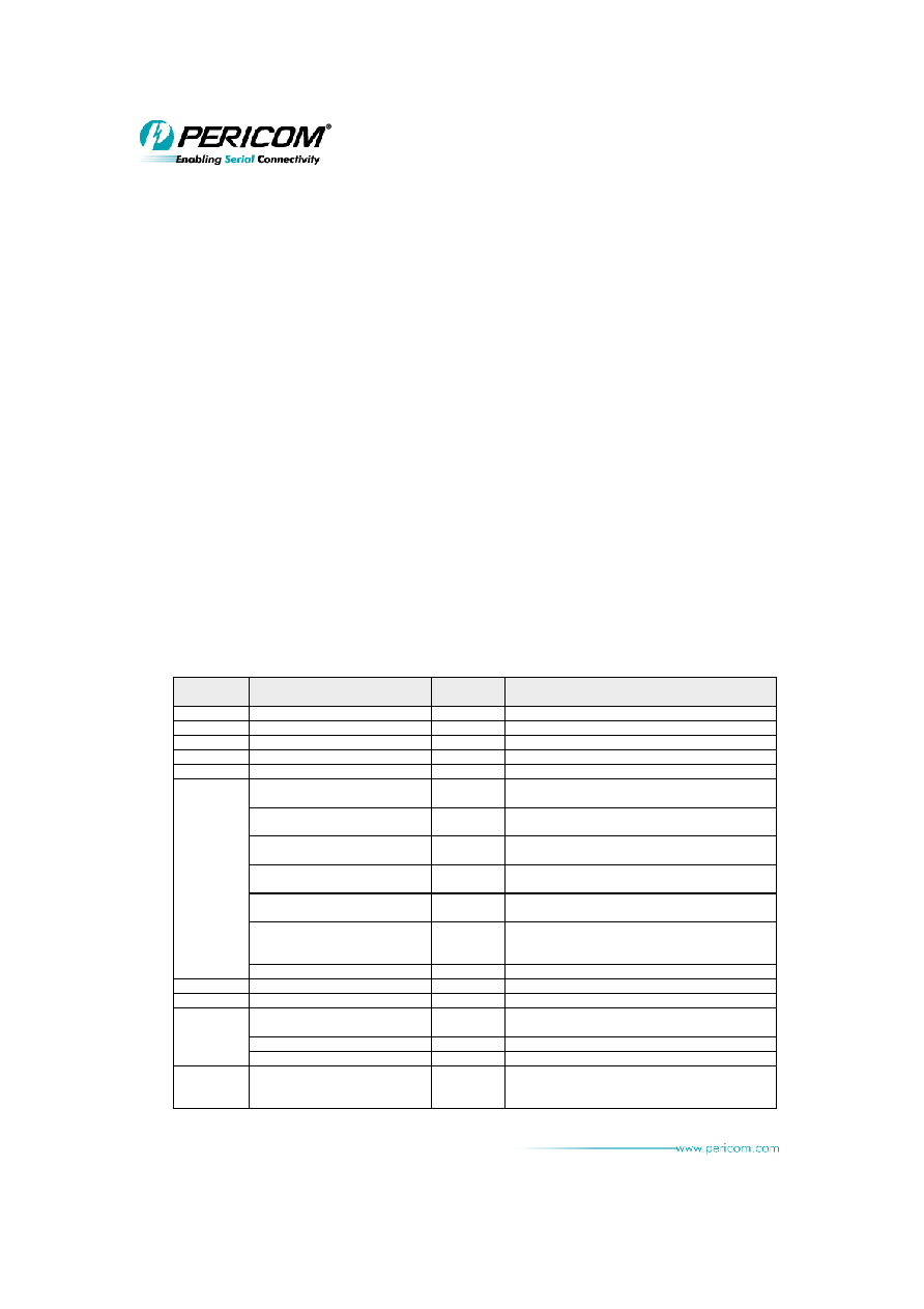
8.3. EEPROM SPACE ADDRESS MAP AND DESCRIPTION
EEPROM
ADDRESS
PCIE REGISTER OFFSET
DEFAULT
Value
DESCRIPTION
00h
A868h
Check Code
02h
Offset 00h bit[15:0]
12D8h
Vendor ID
04h
Offset 00h bit[31:16]
7954h
Device ID
06h
Offset 2Ch bit[15:0]
0000h
Subsytem Vendor ID
08h
Offset 2Ch bit[31:16]
0000h
Subsytem ID
0Ah
Bit[0] - Offset 80h bit[21]
0b
Device Specific Initialization: When set, the DSI is
required.
Bit[3:1] - Offset 80h bit[24:22]
111b
Aux. Current: When set, the I/O bridge needs 375
mA in D3 state.
Bit[4] - Offset 80h bit[25]
1b
D1 Support: When set, this bridge supports D1
Power Management state.
Bit[5] - Offset 80h bit[26]
1b
D2 Support: When set, this bridge supports D2
Power Management state.
Bit[10:6] - Offset 80h bit[31:27]
01000b
PME Support: When set, the PME supports D1 and
D2 Power Management states.
Bit[11] - Offset 84h bit[3]
1b
No Soft Reset: When set, the device does not
trigger the Internal Reset Command during the
transition from D3hot to D0 power state.
Bit[13:12] - Offset A8h bit[14:13]
00b
XPIP CSR0
0Ch
Offset B0h bit[15:0]
0000h
Replay Time-out Counter
0Eh
Offset B0h bit [31:16]
0000h
Acknowledge Latency Timer
10h
Bit[1:0] - Offset ECh bit[11:10]
11b
ASPM Capability Support: When set, this bridge
supports L0s and L1 entry
Bit[4:2] - Offset ECh bit[14:12]
011b
Exit L0s Latency Timer
Bit[7:5] - Offset ECh bit[17:15]
000b
Exit L1 Latency Timer
12h
Offset B4h bit[15:0]
0000h
UART Transmitter Drive Enable:
RS232/422/485-2W/485-4W Selection for UART 0
to 3
13-0093
相關(guān)PDF資料 |
PDF描述 |
|---|---|
| PI7C9X7958ANBE | IC PCIE-TO-UART BRIDGE 160LFBGA |
| PI90LV017AUEX | IC LVDS DIFF LINE DVR 3V 8-MSOP |
| PI90LV01TEX | IC LVDS DIFF LINE DRVR SOT23-5 |
| PI90LV027AW | IC DUAL LVDS LINE DRIVER 8-SOIC |
| PI90LV028AUEX | IC LVDS LINE RCVR DUAL 8-MSOP |
相關(guān)代理商/技術(shù)參數(shù) |
參數(shù)描述 |
|---|---|
| PI7C9X7958AEVB | 制造商:Pericom Semiconductor Corporation 功能描述:7958A EVAL BOARD 制造商:Pericom Semiconductor Corporation 功能描述:EVAL BOARD PI7C9X7958A 制造商:Pericom Semiconductor Corporation 功能描述:8 Port PCI Express UART I/O Bridge Evaluation Board |
| PI7C9X7958ANBE | 功能描述:外圍驅(qū)動(dòng)器與原件 - PCI X1 PCIE-UART 8 Channel Bridge RoHS:否 制造商:PLX Technology 工作電源電壓: 最大工作溫度: 安裝風(fēng)格:SMD/SMT 封裝 / 箱體:FCBGA-1156 封裝:Tray |
| PI7C9X7958ANBE-MOXA | 制造商:Pericom Semiconductor Corporation 功能描述: |
| PI8008 | 制造商:未知廠家 制造商全稱:未知廠家 功能描述:DIGITAL-THERMOMETER |
| PI80N06S4-05 | 制造商:INFINEON 制造商全稱:Infineon Technologies AG 功能描述:OptiMOS-T2 Power-Transistor |
發(fā)布緊急采購(gòu),3分鐘左右您將得到回復(fù)。