- 您現(xiàn)在的位置:買賣IC網(wǎng) > PDF目錄383967 > TSB82AA2I (Texas Instruments, Inc.) 1394b OHCI-LYNX CONTROLLER PDF資料下載
參數(shù)資料
| 型號: | TSB82AA2I |
| 廠商: | Texas Instruments, Inc. |
| 英文描述: | 1394b OHCI-LYNX CONTROLLER |
| 中文描述: | 的1394b OHCI的山貓控制器 |
| 文件頁數(shù): | 35/104頁 |
| 文件大?。?/td> | 461K |
| 代理商: | TSB82AA2I |
第1頁第2頁第3頁第4頁第5頁第6頁第7頁第8頁第9頁第10頁第11頁第12頁第13頁第14頁第15頁第16頁第17頁第18頁第19頁第20頁第21頁第22頁第23頁第24頁第25頁第26頁第27頁第28頁第29頁第30頁第31頁第32頁第33頁第34頁當(dāng)前第35頁第36頁第37頁第38頁第39頁第40頁第41頁第42頁第43頁第44頁第45頁第46頁第47頁第48頁第49頁第50頁第51頁第52頁第53頁第54頁第55頁第56頁第57頁第58頁第59頁第60頁第61頁第62頁第63頁第64頁第65頁第66頁第67頁第68頁第69頁第70頁第71頁第72頁第73頁第74頁第75頁第76頁第77頁第78頁第79頁第80頁第81頁第82頁第83頁第84頁第85頁第86頁第87頁第88頁第89頁第90頁第91頁第92頁第93頁第94頁第95頁第96頁第97頁第98頁第99頁第100頁第101頁第102頁第103頁第104頁
315
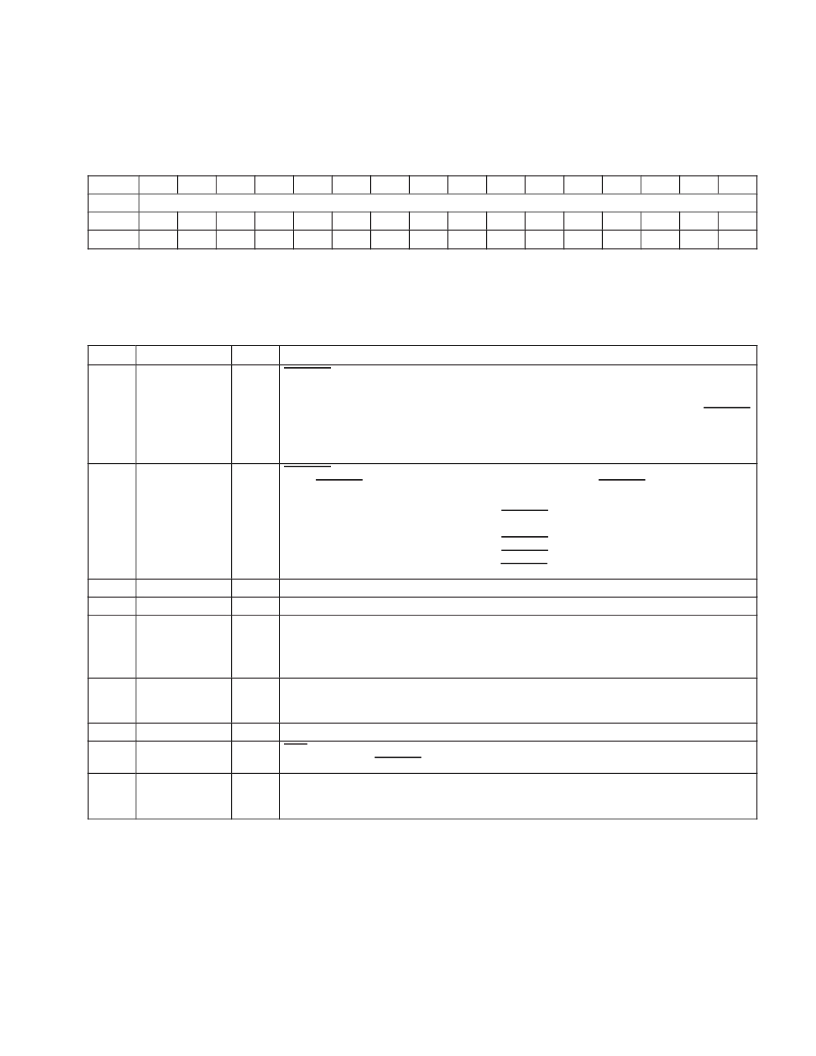
3.19 Power Management Capabilities Register
The power management capabilities register indicates the capabilities of the TSB82AA2 device related to PCI power
management. See Table 317 for a complete description of the register contents.
Bit
15
14
13
12
11
10
9
8
7
6
5
4
3
2
1
0
Name
Power management capabilities
Type
RU
R
R
R
R
R
R
R
R
R
R
R
R
R
R
R
Default
0
1
1
1
1
1
1
0
0
0
0
0
0
0
1
0
Register:
Type:
Offset:
Default:
Power management capabilities
Read/Update, Read-only
46h
7E02h
Table 317. Power Management Capabilities Register Description
BIT
FIELD NAME
TYPE
DESCRIPTION
15
PME_D3COLD
RU
PCI_PME support from D3cold. This bit can be set to 1 or cleared to 0 via bit 15 (PME_D3COLD) in
the miscellaneous configuration register at offset F0h in the PCI configuration space (see Section 3.23,
Miscellaneous Configuration Register
). The miscellaneous configuration register is loaded from ROM.
When this bit is set to 1, it indicates that the TSB82AA2 device is capable of generating a PCI_PME
wake event from D3cold. This bit state is dependent upon the TSB82AA2 VAUX implementation and
may be configured by using bit 15 (PME_D3COLD) in the miscellaneous configuration register (see
Section 3.23).
1411
PME_SUPPORT
R
PCI_PME support. This 4-bit field indicates the power states from which the TSB82AA2 device may
assert PCI_PME. This field returns a value of 1111b, indicating that PCI_PME may be asserted from
the D3hot, D2, D1, and D0 power states.
Bit 14 contains the value 1 to indicate that the PCI_PME signal can be asserted from the D3hot
state.
Bit 13 contains the value 1 to indicate that the PCI_PME signal can be asserted from the D2 state.
Bit 12 contains the value 1 to indicate that the PCI_PME signal can be asserted from the D1 state.
Bit 11 contains the value 1 to indicate that the PCI_PME signal can be asserted from the D0 state.
10
D2_SUPPORT
R
D2 support. Bit 10 is hardwired to 1, indicating that the function supports the D2 device power state.
9
D1_SUPPORT
R
D1 support. Bit 9 is hardwired to 1, indicating that the TSB82AA2 device supports the D1 power state.
86
AUX_CURRENT
R
Auxiliary current. This 3-bit field reports the 3.3-VAUX auxiliary current requirements. When bit 15
(PME_D3COLD) is cleared, this field returns 000b; otherwise, it returns 001b.
000b = Self-powered
001b = 55 mA (3.3-VAUX maximum current required)
Device-specific initialization. Bit 5 returns 0 when read, indicating that the TSB82AA2 device does not
require special initialization beyond the standard PCI configuration header before a generic class
driver is able to use it.
5
DSI
R
4
RSVD
R
Reserved. Bit 4 returns 0 when read.
3
PME_CLK
R
PME clock. Bit 3 returns 0 when read, indicating that no host bus clock is required for the TSB82AA2
device to generate PCI_PME.
20
PM_VERSION
R
Power-management version. This field returns 010b when read, indicating that the TSB82AA2 device
is compatible with the registers described in the
PCI Bus Power Management Interface Specification
(Revision 1.1).
相關(guān)PDF資料 |
PDF描述 |
|---|---|
| TSC2200EVM | TSC2200 Touch Screen Controller Evaluation Module(TSC2200觸摸屏控制器評估模塊) |
| TSC427CBA | Dual Power MOSFET Drivers |
| TSC427CPA | Dual Power MOSFET Drivers |
| TSC428CBA | Dual Power MOSFET Drivers |
| TSC426CBA | Dual Power MOSFET Drivers |
相關(guān)代理商/技術(shù)參數(shù) |
參數(shù)描述 |
|---|---|
| TSB82AA2IPGE | 功能描述:接口 - 專用 OHCI-Lynx Controller RoHS:否 制造商:Texas Instruments 產(chǎn)品類型:1080p60 Image Sensor Receiver 工作電源電壓:1.8 V 電源電流:89 mA 最大功率耗散: 最大工作溫度:+ 85 C 安裝風(fēng)格:SMD/SMT 封裝 / 箱體:BGA-59 |
| TSB82AA2IPGEEP | 功能描述:1394 接口集成電路 Mil Enh 1394b OHCI- Lynx Cntrlr RoHS:否 制造商:Texas Instruments 類型:Link Layer Controller 工作電源電壓: 封裝 / 箱體:LQFP 封裝:Tray |
| TSB82AA2PGE | 功能描述:1394 接口集成電路 OHCI-Lynx Controller RoHS:否 制造商:Texas Instruments 類型:Link Layer Controller 工作電源電壓: 封裝 / 箱體:LQFP 封裝:Tray |
| TSB82AA2PGEG4 | 功能描述:1394 接口集成電路 OHCI-Lynx Controller RoHS:否 制造商:Texas Instruments 類型:Link Layer Controller 工作電源電壓: 封裝 / 箱體:LQFP 封裝:Tray |
| TSB82AA2ZGW | 功能描述:1394 接口集成電路 OHCI-Lynx Controller RoHS:否 制造商:Texas Instruments 類型:Link Layer Controller 工作電源電壓: 封裝 / 箱體:LQFP 封裝:Tray |
發(fā)布緊急采購,3分鐘左右您將得到回復(fù)。