- 您現(xiàn)在的位置:買賣IC網(wǎng) > PDF目錄384032 > TVP3026-175M (Texas Instruments, Inc.) Video Interface PALETTE Exract(組合像素模式視頻接口調(diào)色器) PDF資料下載
參數(shù)資料
| 型號: | TVP3026-175M |
| 廠商: | Texas Instruments, Inc. |
| 英文描述: | Video Interface PALETTE Exract(組合像素模式視頻接口調(diào)色器) |
| 中文描述: | 視頻接口調(diào)色板Exract(組合像素模式視頻接口調(diào)色器) |
| 文件頁數(shù): | 18/107頁 |
| 文件大小: | 707K |
| 代理商: | TVP3026-175M |
第1頁第2頁第3頁第4頁第5頁第6頁第7頁第8頁第9頁第10頁第11頁第12頁第13頁第14頁第15頁第16頁第17頁當(dāng)前第18頁第19頁第20頁第21頁第22頁第23頁第24頁第25頁第26頁第27頁第28頁第29頁第30頁第31頁第32頁第33頁第34頁第35頁第36頁第37頁第38頁第39頁第40頁第41頁第42頁第43頁第44頁第45頁第46頁第47頁第48頁第49頁第50頁第51頁第52頁第53頁第54頁第55頁第56頁第57頁第58頁第59頁第60頁第61頁第62頁第63頁第64頁第65頁第66頁第67頁第68頁第69頁第70頁第71頁第72頁第73頁第74頁第75頁第76頁第77頁第78頁第79頁第80頁第81頁第82頁第83頁第84頁第85頁第86頁第87頁第88頁第89頁第90頁第91頁第92頁第93頁第94頁第95頁第96頁第97頁第98頁第99頁第100頁第101頁第102頁第103頁第104頁第105頁第106頁第107頁
2–4
2.1.4
The registers for the three cursor colors and the overscan border color are accessed through the direct
register map. See Section 2.9, Overscan Borderdescription and subsection 2.7.3, Three-Color 64 X 64
Cursor for use of the cursor colors.
Cursor and Overscan Color Registers
The color write address register (direct register: 0100) must be initialized before writing to the color registers.
The lower two bits of this register select one of the four color registers according to Table 2–4. The selected
24-bit color register is loaded a byte at a time by writing a sequence of three bytes (red, green, and blue)
to the color data register (direct register: 0101). After the blue byte is written, the color address register
increments to the next color. All four colors may be loaded with a single write to the color write address
register followed by 12 consecutive writes to the color data register.
The color read address register (direct register: 0111) must be initialized before reading from the color
registers. The lower two bits of this register select one of the four color registers according to Table 2–4. Next,
the color data register (direct register: 0101) is read three times, producing red, green, and blue bytes from
the selected register. After the blue byte is read, the color address register is incremented to the next color.
All four colors may be read with a single write to the color read address register followed by 12 consecutive
reads of the color data register.
The sequence followed by the color address register is overscan color, cursor color 0, cursor color 1, cursor
color 2, . . ., etc. The starting point depends on what was written to the color write address or color read
address register.
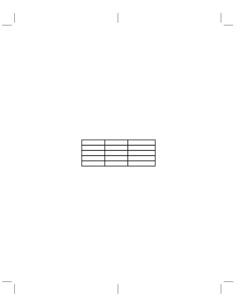
Table 2–4. Color Register Address Format
BIT 1
BIT 0
REGISTER
0
0
Overscan color
0
1
Cursor color 0
1
0
Cursor color 1
1
1
Cursor color 2
2.2
The color-palette RAM is addressed by an internal 8-bit address register for reading/writing data from/to the
RAM. This register is automatically incremented following a RAM transfer, allowing the entire palette to be
read/written with only one access of the address register. When the address register increments beyond
the last location in RAM, it is reset to the first location (address 0). All read and write accesses to the RAM
are asynchronous to the internal clocks but are performed within one dot clock. Therefore, read/write
accesses do not cause any noticeable disturbance on the display.
Color-Palette RAM
The color palette RAM is 24 bits wide for each location and 8 bits wide for each color. Since a MPU access
is 8 bits wide, the color data stored in the palette is eight bits when the 6-bit mode is chosen. When the 6-bit
mode is chosen, the two MSBs of color data in the palette have the values previously written. However, when
they are read back in the 6-bit mode, the two MSBs are zeros to be compatible with INMOS IMSG176 and
Brooktree Bt176. The output multiplexer shifts the six LSB bits to the six MSB positions and fills the two LSBs
with 0s after the color palette. The multiplexer then feeds the data to the DAC. The test mode data register
and the cyclic redundancy check (CRC) calculation both take data after the output multiplexer, enabling total
system verification. The color palette access is described in the following two sections, and it is fully
compatible with IMSG176/8 and Bt476/8.
相關(guān)PDF資料 |
PDF描述 |
|---|---|
| TVP3026-220 | Video Interface PALETTE Exract(組合像素模式視頻接口調(diào)色器) |
| TVP3026-250 | Video Interface PALETTE Exract(組合像素模式視頻接口調(diào)色器) |
| TX24 | 60.8 MM 5 X 8 DOT MATRIX DISPLAYS |
| TXB0102DCTR | 2-BIT BIDIRECTIONAL VOLTAGE-LEVEL TRANSLATOR WITH AUTO DIRECTION SENSING AND 【15-kV ESD PROTECTION |
| TXB0102DCTT | 2-BIT BIDIRECTIONAL VOLTAGE-LEVEL TRANSLATOR WITH AUTO DIRECTION SENSING AND 【15-kV ESD PROTECTION |
相關(guān)代理商/技術(shù)參數(shù) |
參數(shù)描述 |
|---|---|
| TVP3026-175MDN | 制造商:未知廠家 制造商全稱:未知廠家 功能描述:Video DAC with Color Palette (RAMDAC) |
| TVP3026-175MHFG | 制造商:未知廠家 制造商全稱:未知廠家 功能描述:Video DAC with Color Palette (RAMDAC) |
| TVP3026-175MHFGB | 制造商:未知廠家 制造商全稱:未知廠家 功能描述:Video DAC with Color Palette (RAMDAC) |
| TVP3026-175PCE | 制造商:Rochester Electronics LLC 功能描述:- Bulk |
| TVP3026-220AMDN | 制造商:TI 制造商全稱:Texas Instruments 功能描述:Video Interface Palette |
發(fā)布緊急采購,3分鐘左右您將得到回復(fù)。