- 您現(xiàn)在的位置:買賣IC網(wǎng) > PDF目錄383838 > ST20GP1 MAX 7000 CPLD 256 MC 208-PQFP PDF資料下載
參數(shù)資料
| 型號: | ST20GP1 |
| 英文描述: | MAX 7000 CPLD 256 MC 208-PQFP |
| 中文描述: | GPS處理器 |
| 文件頁數(shù): | 74/116頁 |
| 文件大?。?/td> | 1107K |
| 代理商: | ST20GP1 |
第1頁第2頁第3頁第4頁第5頁第6頁第7頁第8頁第9頁第10頁第11頁第12頁第13頁第14頁第15頁第16頁第17頁第18頁第19頁第20頁第21頁第22頁第23頁第24頁第25頁第26頁第27頁第28頁第29頁第30頁第31頁第32頁第33頁第34頁第35頁第36頁第37頁第38頁第39頁第40頁第41頁第42頁第43頁第44頁第45頁第46頁第47頁第48頁第49頁第50頁第51頁第52頁第53頁第54頁第55頁第56頁第57頁第58頁第59頁第60頁第61頁第62頁第63頁第64頁第65頁第66頁第67頁第68頁第69頁第70頁第71頁第72頁第73頁當前第74頁第75頁第76頁第77頁第78頁第79頁第80頁第81頁第82頁第83頁第84頁第85頁第86頁第87頁第88頁第89頁第90頁第91頁第92頁第93頁第94頁第95頁第96頁第97頁第98頁第99頁第100頁第101頁第102頁第103頁第104頁第105頁第106頁第107頁第108頁第109頁第110頁第111頁第112頁第113頁第114頁第115頁第116頁
ST20-GP1
74/116
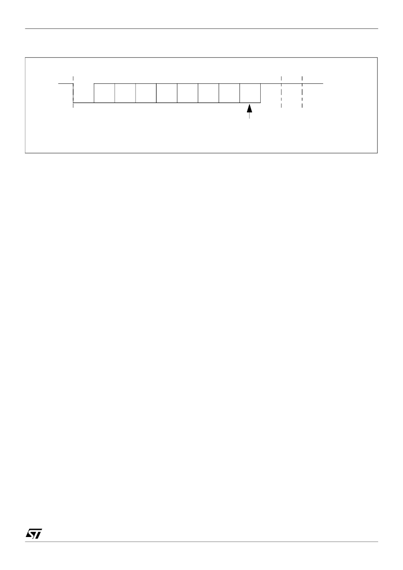
Figure 13.2 8-bit data frames
9-bit data frames
9-bit data frames consist of:
nine data bits
D0-8
;
eight data bits
D0-7
plus an automatically generated parity bit;
eight data bits
D0-7
plus a wake-up bit.
Parity may be odd or even, depending on the
ParityOdd
bit in the
ASCControl
register. An even
parity bit will be set, if the modulo-2-sum of the eight data bits is 1. An odd parity bit will be cleared
in this case. The parity error flag (
ParityError
) will be set if a wrong parity bit is received. The parity
bit itself will be stored in bit 8 of the
ASCRxBuffer
register, see Table 13.4.
In wake-up mode, received frames are only transferred to the receive buffer register if the ninth bit
(the wake-up bit) is 1. If this bit is 0, no receive interrupt request will be activated and no data will
be transferred. This feature can be used to control communication in multi-processor systems.
When the master processor wants to transmit a block of data to one of several slaves, it first sends
out an address byte which identifies the target slave. An address byte differs from a data byte in
that the additional ninth bit is a 1 for an address byte and a 0 for a data byte, so no slave will be
interrupted by a data byte. An address byte will interrupt all slaves (operating in 8-bit data + wake-
up bit mode), so each slave can examine the 8 least significant bits (LSBs) of the received
character (the address). The addressed slave will switch to 9-bit data mode, which enables it to
receive the data bytes that will be coming (with the wake-up bit cleared). The slaves that are not
being addressed remain in 8-bit data + wake-up bit mode, ignoring the following data bytes.
2nd
stop
bit
1st
stop
bit
start
bit
D0
(LSB)
8th
bit
Data bit (
D7
)
Parity bit
相關PDF資料 |
PDF描述 |
|---|---|
| ST20GP6 | MAX 7000 CPLD 256 MC 208-RQFP |
| ST25C02AB1 | IC FLEX 6000 FPGA 16K 144-TQFP |
| ST25C02AB6 | Stratix FPGA 25K FBGA-672 |
| ST25C02AM1 | IC ACEX 1K FPGA 100K 208-PQFP |
| ST25C02AM6 | Cyclone II FPGA 20K FBGA-256 |
相關代理商/技術參數(shù) |
參數(shù)描述 |
|---|---|
| ST20-GP1 | 制造商:STMICROELECTRONICS 制造商全稱:STMicroelectronics 功能描述:GPS PROCESSOR |
| ST20GP1X33S | 制造商:STMICROELECTRONICS 制造商全稱:STMicroelectronics 功能描述:GPS PROCESSOR |
| ST20GP6 | 制造商:未知廠家 制造商全稱:未知廠家 功能描述:GPS PROCESSOR |
| ST20-GP6 | 制造商:STMICROELECTRONICS 制造商全稱:STMicroelectronics 功能描述:GPS PROCESSOR |
| ST20GP6CT33S | 制造商:STMICROELECTRONICS 制造商全稱:STMicroelectronics 功能描述:GPS PROCESSOR |
發(fā)布緊急采購,3分鐘左右您將得到回復。