- 您現在的位置:買賣IC網 > PDF目錄383838 > ST20GP1 MAX 7000 CPLD 256 MC 208-PQFP PDF資料下載
參數資料
| 型號: | ST20GP1 |
| 英文描述: | MAX 7000 CPLD 256 MC 208-PQFP |
| 中文描述: | GPS處理器 |
| 文件頁數: | 59/116頁 |
| 文件大小: | 1107K |
| 代理商: | ST20GP1 |
第1頁第2頁第3頁第4頁第5頁第6頁第7頁第8頁第9頁第10頁第11頁第12頁第13頁第14頁第15頁第16頁第17頁第18頁第19頁第20頁第21頁第22頁第23頁第24頁第25頁第26頁第27頁第28頁第29頁第30頁第31頁第32頁第33頁第34頁第35頁第36頁第37頁第38頁第39頁第40頁第41頁第42頁第43頁第44頁第45頁第46頁第47頁第48頁第49頁第50頁第51頁第52頁第53頁第54頁第55頁第56頁第57頁第58頁當前第59頁第60頁第61頁第62頁第63頁第64頁第65頁第66頁第67頁第68頁第69頁第70頁第71頁第72頁第73頁第74頁第75頁第76頁第77頁第78頁第79頁第80頁第81頁第82頁第83頁第84頁第85頁第86頁第87頁第88頁第89頁第90頁第91頁第92頁第93頁第94頁第95頁第96頁第97頁第98頁第99頁第100頁第101頁第102頁第103頁第104頁第105頁第106頁第107頁第108頁第109頁第110頁第111頁第112頁第113頁第114頁第115頁第116頁
ST20-GP1
59/116
status of the lock and stall bits. Table 9.6 shows the format of the
EMIConfigStatus
register.
EMIConfigStall register
The
EMIConfigStall
register can be used to stall the EMI. When set it prevents the EMI from
accepting further requests from the CPU or communications subsystems. Its main use is intended
to be in systems which anticipate turning the power off; the EMI must be inactive during such an
event, otherwise battery backed memory may be corrupted.
This register, once set, can only be cleared by resetting the ST20-GP1.
9.6
Reset and bootstrap behavior
Table 9.8 shows the state of the EMI signals during reset.
MemAddr2-19
are driven with a copy of
the value on the internal memory bus2-19.
Table 9.9 shows the configuration values for all banks during and after reset. If the
BootSource0-1
pins indicate that the ST20-GP1 will boot from ROM, the
BusWidth
is set to the correct value as
the ST20-GP1 comes out of reset.
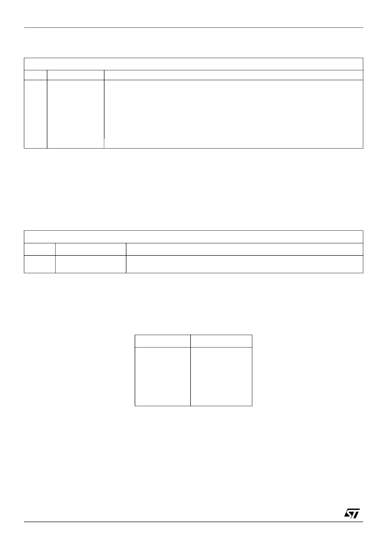
EMIConfigStatus
EMI base address + #20
Read only
Bit
0
1
2
3
4
5
31:6
Bit field
WrittenBank0
WrittenBank1
WrittenBank2
WrittenBank3
WriteLock
MemStall
Function
Bank 0 configuration has been written to using a devsw instruction.
Bank 1 configuration has been written to using a devsw instruction.
Bank 2 configuration has been written to using a devsw instruction.
Bank 3 configuration has been written to using a devsw instruction.
EMIConfigData0-3
registers are write protected.
EMIConfigStall
has been set.
Reserved
Table 9.6
EMIConfigStatus
register format
EMIConfigStall
EMI base address + #30
Write only
Bit
Bit field
Function
0
EMIStall
When set, this bit prevents the arbiter from granting any more accesses to the
memory subsystem.
Table 9.7
EMIConfigStall
register format
Pins
Value
MemAddr2-19
MemAddr1
notMemCE0-3
notMemOE0-1
notMemWB0-1
MemData0-15
Table 9.8 EMI signal values during reset
Valid
High
All high
All high
All high
High impedance
相關PDF資料 |
PDF描述 |
|---|---|
| ST20GP6 | MAX 7000 CPLD 256 MC 208-RQFP |
| ST25C02AB1 | IC FLEX 6000 FPGA 16K 144-TQFP |
| ST25C02AB6 | Stratix FPGA 25K FBGA-672 |
| ST25C02AM1 | IC ACEX 1K FPGA 100K 208-PQFP |
| ST25C02AM6 | Cyclone II FPGA 20K FBGA-256 |
相關代理商/技術參數 |
參數描述 |
|---|---|
| ST20-GP1 | 制造商:STMICROELECTRONICS 制造商全稱:STMicroelectronics 功能描述:GPS PROCESSOR |
| ST20GP1X33S | 制造商:STMICROELECTRONICS 制造商全稱:STMicroelectronics 功能描述:GPS PROCESSOR |
| ST20GP6 | 制造商:未知廠家 制造商全稱:未知廠家 功能描述:GPS PROCESSOR |
| ST20-GP6 | 制造商:STMICROELECTRONICS 制造商全稱:STMicroelectronics 功能描述:GPS PROCESSOR |
| ST20GP6CT33S | 制造商:STMICROELECTRONICS 制造商全稱:STMicroelectronics 功能描述:GPS PROCESSOR |
發(fā)布緊急采購,3分鐘左右您將得到回復。