- 您現(xiàn)在的位置:買賣IC網(wǎng) > PDF目錄371670 > 83C795 (SMSC Corporation) Ethernet System Controller PDF資料下載
參數(shù)資料
| 型號(hào): | 83C795 |
| 廠商: | SMSC Corporation |
| 英文描述: | Ethernet System Controller |
| 中文描述: | 以太網(wǎng)系統(tǒng)控制器 |
| 文件頁數(shù): | 36/136頁 |
| 文件大?。?/td> | 1996K |
| 代理商: | 83C795 |
第1頁第2頁第3頁第4頁第5頁第6頁第7頁第8頁第9頁第10頁第11頁第12頁第13頁第14頁第15頁第16頁第17頁第18頁第19頁第20頁第21頁第22頁第23頁第24頁第25頁第26頁第27頁第28頁第29頁第30頁第31頁第32頁第33頁第34頁第35頁當(dāng)前第36頁第37頁第38頁第39頁第40頁第41頁第42頁第43頁第44頁第45頁第46頁第47頁第48頁第49頁第50頁第51頁第52頁第53頁第54頁第55頁第56頁第57頁第58頁第59頁第60頁第61頁第62頁第63頁第64頁第65頁第66頁第67頁第68頁第69頁第70頁第71頁第72頁第73頁第74頁第75頁第76頁第77頁第78頁第79頁第80頁第81頁第82頁第83頁第84頁第85頁第86頁第87頁第88頁第89頁第90頁第91頁第92頁第93頁第94頁第95頁第96頁第97頁第98頁第99頁第100頁第101頁第102頁第103頁第104頁第105頁第106頁第107頁第108頁第109頁第110頁第111頁第112頁第113頁第114頁第115頁第116頁第117頁第118頁第119頁第120頁第121頁第122頁第123頁第124頁第125頁第126頁第127頁第128頁第129頁第130頁第131頁第132頁第133頁第134頁第135頁第136頁
5.2
LAN CONTROLLER REGISTER
DESCRIPTIONS
To simplify the programming model for the LAN
controller and retain compatibility with the SMC
83C690 LAN Controller, the internal registers are
divided into two address maps. The default address
map is used for Ring-style buffering (like the
83C690). Those registers needed for linked-list
buffering are grouped together in the alternate
address map and are enabled through the
Enhancement (ENH) register described starting on
page 26.
E ach map provides access to all registers
necessary for operating that particular buffering
mode. Many registers are visible in both maps,
although not always at the same address in each.
To facilitate manufacturing test of the device, many
internal registers can be accessed in one or both of
these maps. Within each map, the registers are
organized into 4 pages of 16 registers each. Only
one page is visible at a time. Page selection is made
through the Command (CMD) register described
starting on page 24.
The addresses listed in this specification are in an
abbreviated form. The first hex digit is really a
two-bit ’page’ value which is written into the LAN
COMMAND (CMD) register to access the 16
registers visible for that page. The digits after the
colon are the offset within the 83C795’s LAN
Controller I/O segment in this manner:
pageoffset
To determine the correct address, you must first
know the 83C795’s base address then select the
correct page and finally select the correct offset. So,
for example, "3:1C" indicates that the address for
this particular register is found on page 3 at the
offset value 1C.
In the following descriptions, the most significant bit
position is numbered ’7’. The line labelled RESET
shows the initial values loaded into the register by
assertion of the RESET pin. The symbol ’0’ denotes
void bits which always return zero when read.
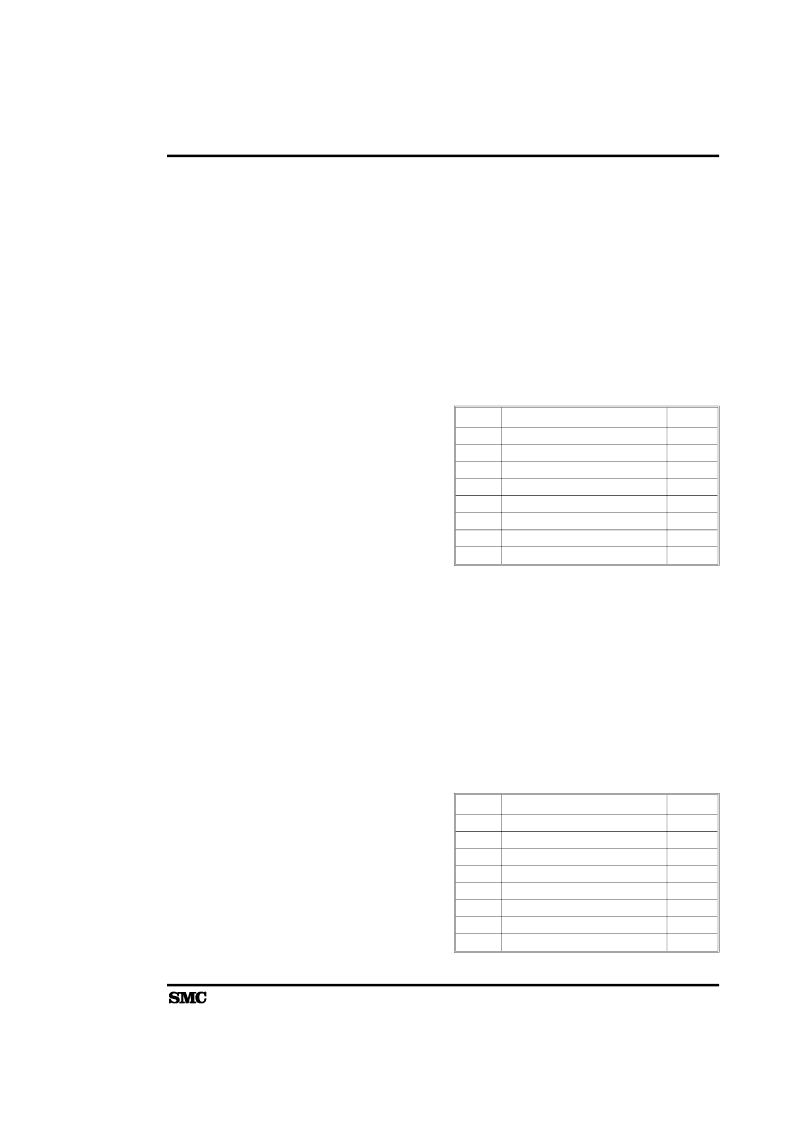
5.2.1
ALICNT - Alignment Error Counter
Register
Normal Map Read Port = 0:1D Link-List Map Read
Port = 0:1D
This register is the alignment error counter. It is
incremented by the receive unit when a packet is
received with a frame alignment error. Only packets
whose addresses are recognized will be included
in this tally. The counter will increment to 255 and
stop if additional alignment errors are detected. The
counter is cleared when read.
BIT
7
6
5
4
3
2
1
0
ALICNT
RESET
0
0
0
0
0
0
0
0
CT7
CT6
CT5
CT4
CT3
CT2
CT1
CT0
5.2.2
BOUND - Receive Boundary Page
Register
Normal Map Read/Write Port = 0:13
The Receive Boundary Page Register points to the
oldest used receive buffer in the ring. It is used to
prevent overflow in the buffer ring. The DMA
compares the contents of this register to the next
buffer address when linking buffers together for
storage of a received frame. If the contents match
the next buffer address, the DMA operation is
aborted. Only A08-A15 are specified since all
buffers are aligned on 256-byte boundaries. For
more information, refer to page 85.
BIT
7
6
5
4
3
2
1
0
BOUND
RESET
X
X
X
X
X
X
X
X
A15
A14
A13
A12
A11
A10
A09
A08
ETHERNET SYSTEM CONTROLLER REGISTERS
83C795
23
相關(guān)PDF資料 |
PDF描述 |
|---|---|
| 84063 | The Constituents of Semiconductor Components |
| 8406601QA | CMOS Programmable Peripheral Interface |
| 8406601XA | CMOS Programmable Peripheral Interface |
| 8406602XA | CMOS Programmable Peripheral Interface |
| 8406602QA | CMOS Programmable Peripheral Interface |
相關(guān)代理商/技術(shù)參數(shù) |
參數(shù)描述 |
|---|---|
| 83C800-009 | 制造商:DRS 功能描述: |
| 83C825EQFP | 制造商:SMSC 功能描述: |
| 83C845 | 制造商:PHILIPS 制造商全稱:NXP Semiconductors 功能描述:Microcontrollers for TV and video MTV |
| 83C851 | 制造商:PHILIPS 制造商全稱:NXP Semiconductors 功能描述:CMOS single-chip 8-bit microcontroller with on-chip EEPROM |
| 83C852DIE | 制造商:未知廠家 制造商全稱:未知廠家 功能描述:8-Bit Microcontroller |
發(fā)布緊急采購(gòu),3分鐘左右您將得到回復(fù)。