- 您現(xiàn)在的位置:買(mǎi)賣(mài)IC網(wǎng) > PDF目錄371436 > 28F640C3 (Intel Corp.) 3 Volt Advanced Boot Block Flash Memory(3 V 高級(jí)快速引導(dǎo)塊閃速存儲(chǔ)器) PDF資料下載
參數(shù)資料
| 型號(hào): | 28F640C3 |
| 廠商: | Intel Corp. |
| 英文描述: | 3 Volt Advanced Boot Block Flash Memory(3 V 高級(jí)快速引導(dǎo)塊閃速存儲(chǔ)器) |
| 中文描述: | 3伏高級(jí)啟動(dòng)塊閃存(3伏高級(jí)快速引導(dǎo)塊閃速存儲(chǔ)器) |
| 文件頁(yè)數(shù): | 26/70頁(yè) |
| 文件大小: | 894K |
| 代理商: | 28F640C3 |
第1頁(yè)第2頁(yè)第3頁(yè)第4頁(yè)第5頁(yè)第6頁(yè)第7頁(yè)第8頁(yè)第9頁(yè)第10頁(yè)第11頁(yè)第12頁(yè)第13頁(yè)第14頁(yè)第15頁(yè)第16頁(yè)第17頁(yè)第18頁(yè)第19頁(yè)第20頁(yè)第21頁(yè)第22頁(yè)第23頁(yè)第24頁(yè)第25頁(yè)當(dāng)前第26頁(yè)第27頁(yè)第28頁(yè)第29頁(yè)第30頁(yè)第31頁(yè)第32頁(yè)第33頁(yè)第34頁(yè)第35頁(yè)第36頁(yè)第37頁(yè)第38頁(yè)第39頁(yè)第40頁(yè)第41頁(yè)第42頁(yè)第43頁(yè)第44頁(yè)第45頁(yè)第46頁(yè)第47頁(yè)第48頁(yè)第49頁(yè)第50頁(yè)第51頁(yè)第52頁(yè)第53頁(yè)第54頁(yè)第55頁(yè)第56頁(yè)第57頁(yè)第58頁(yè)第59頁(yè)第60頁(yè)第61頁(yè)第62頁(yè)第63頁(yè)第64頁(yè)第65頁(yè)第66頁(yè)第67頁(yè)第68頁(yè)第69頁(yè)第70頁(yè)
28F800C3, 28F160C3, 28F320C3, 28F640C3
20
3UHOLPLQDU\
The 12 V V
PP
mode enhances programming performance during the short period of time typically
found in manufacturing processes; however, it is not intended for extended use. 12 V may be
applied to V
PP
during program and erase operations for a maximum of 1000 cycles on the main
blocks and 2500 cycles on the parameter blocks. V
PP
may be connected to 12 V for a total of 80
hours maximum. Stressing the device beyond these limits may cause permanent damage.
3.5.2
V
PP
≤
V
PPLK
for Complete Protection
In addition to the flexible block locking, the V
PP
programming voltage can be held low for absolute
hardware write protection of all blocks in the flash device. When V
PP
is below V
PPLK
, any
program or erase operation will result in a error, prompting the corresponding status register bit
(SR.3) to be set.
0645_06
NOTE:
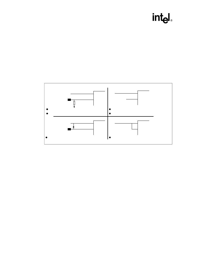
1. A resistor can be used if the V
supply can sink adequate current based on resistor value. See AP-657
Designing with the Advanced+ Boot Block Flash Memory Architecturefor details.
3.6
Power Consumption
Intel Flash devices have a tiered approach to power savings that can significantly reduce overall
system power consumption. The Automatic Power Savings (APS) feature reduces power
consumption when the device is selected but idle. If the CE# is deasserted, the flash enters its
standby mode, where current consumption is even lower. The combination of these features can
minimize memory power consumption, and therefore, overall system power consumption.
3.6.1
Active Power (Program/Erase/Read)
With CE# at a logic
-
low level and RP# at a logic
-
high level, the device is in the active mode. Refer
to the DC Characteristic tables for I
CC
current values. Active power is the largest contributor to
overall system power consumption. Minimizing the active current could have a profound effect on
system power consumption, especially for battery
-
operated devices.
Figure 5. Example Power Supply Configurations
V
CC
V
PP
12 V Fast Programming
Absolute Write Protection With V
PP
≤
V
PPLK
System Supply
12 V Supply
10
≤
K
V
CC
V
PP
System Supply
12 V Supply
Low Voltage and 12 V Fast Programming
V
CC
V
PP
System Supply
Prot#
(Logic Signal)
V
CC
V
PP
System Supply
Low-Voltage Programming
Low-Voltage Programming
Absolute Write Protection via Logic Signal
(Note 1)
相關(guān)PDF資料 |
PDF描述 |
|---|---|
| 28F640J3C-120 | Intel StrataFlash Memory (J3) |
| 28LV64A | 64K (8K x 8) Low Voltage CMOS EEPROM(低壓,64K位, CMOS 并行EEPROM) |
| 28M0U | 60V 300mA MONOLITHIC DIODE ARRAY |
| 28M0DC | 60V 300mA MONOLITHIC DIODE ARRAY |
| 28M0DS | 60V 300mA MONOLITHIC DIODE ARRAY |
相關(guān)代理商/技術(shù)參數(shù) |
參數(shù)描述 |
|---|---|
| 28F640C3BC80 | 制造商: 功能描述: 制造商:undefined 功能描述: |
| 28F640J3C120 | 制造商: 功能描述: 制造商:undefined 功能描述: |
| 28F640J3C-120 | 制造商: 功能描述: 制造商:undefined 功能描述: |
| 28F640J3D75 | 制造商:Intel 功能描述: 制造商: 功能描述: 制造商:undefined 功能描述: |
| 28F640J5 | 制造商:INTEL 制造商全稱:Intel Corporation 功能描述:5 Volt Intel StrataFlash? Memory |
發(fā)布緊急采購(gòu),3分鐘左右您將得到回復(fù)。