- 您現(xiàn)在的位置:買賣IC網(wǎng) > PDF目錄370849 > M37902FJCHP (Mitsubishi Electric Corporation) SINGLE-CHIP 16-BIT CMOS MICROCOMPUTER PDF資料下載
參數(shù)資料
| 型號(hào): | M37902FJCHP |
| 廠商: | Mitsubishi Electric Corporation |
| 英文描述: | SINGLE-CHIP 16-BIT CMOS MICROCOMPUTER |
| 中文描述: | 單片16位CMOS微機(jī) |
| 文件頁(yè)數(shù): | 141/143頁(yè) |
| 文件大?。?/td> | 1463K |
| 代理商: | M37902FJCHP |
第1頁(yè)第2頁(yè)第3頁(yè)第4頁(yè)第5頁(yè)第6頁(yè)第7頁(yè)第8頁(yè)第9頁(yè)第10頁(yè)第11頁(yè)第12頁(yè)第13頁(yè)第14頁(yè)第15頁(yè)第16頁(yè)第17頁(yè)第18頁(yè)第19頁(yè)第20頁(yè)第21頁(yè)第22頁(yè)第23頁(yè)第24頁(yè)第25頁(yè)第26頁(yè)第27頁(yè)第28頁(yè)第29頁(yè)第30頁(yè)第31頁(yè)第32頁(yè)第33頁(yè)第34頁(yè)第35頁(yè)第36頁(yè)第37頁(yè)第38頁(yè)第39頁(yè)第40頁(yè)第41頁(yè)第42頁(yè)第43頁(yè)第44頁(yè)第45頁(yè)第46頁(yè)第47頁(yè)第48頁(yè)第49頁(yè)第50頁(yè)第51頁(yè)第52頁(yè)第53頁(yè)第54頁(yè)第55頁(yè)第56頁(yè)第57頁(yè)第58頁(yè)第59頁(yè)第60頁(yè)第61頁(yè)第62頁(yè)第63頁(yè)第64頁(yè)第65頁(yè)第66頁(yè)第67頁(yè)第68頁(yè)第69頁(yè)第70頁(yè)第71頁(yè)第72頁(yè)第73頁(yè)第74頁(yè)第75頁(yè)第76頁(yè)第77頁(yè)第78頁(yè)第79頁(yè)第80頁(yè)第81頁(yè)第82頁(yè)第83頁(yè)第84頁(yè)第85頁(yè)第86頁(yè)第87頁(yè)第88頁(yè)第89頁(yè)第90頁(yè)第91頁(yè)第92頁(yè)第93頁(yè)第94頁(yè)第95頁(yè)第96頁(yè)第97頁(yè)第98頁(yè)第99頁(yè)第100頁(yè)第101頁(yè)第102頁(yè)第103頁(yè)第104頁(yè)第105頁(yè)第106頁(yè)第107頁(yè)第108頁(yè)第109頁(yè)第110頁(yè)第111頁(yè)第112頁(yè)第113頁(yè)第114頁(yè)第115頁(yè)第116頁(yè)第117頁(yè)第118頁(yè)第119頁(yè)第120頁(yè)第121頁(yè)第122頁(yè)第123頁(yè)第124頁(yè)第125頁(yè)第126頁(yè)第127頁(yè)第128頁(yè)第129頁(yè)第130頁(yè)第131頁(yè)第132頁(yè)第133頁(yè)第134頁(yè)第135頁(yè)第136頁(yè)第137頁(yè)第138頁(yè)第139頁(yè)第140頁(yè)當(dāng)前第141頁(yè)第142頁(yè)第143頁(yè)
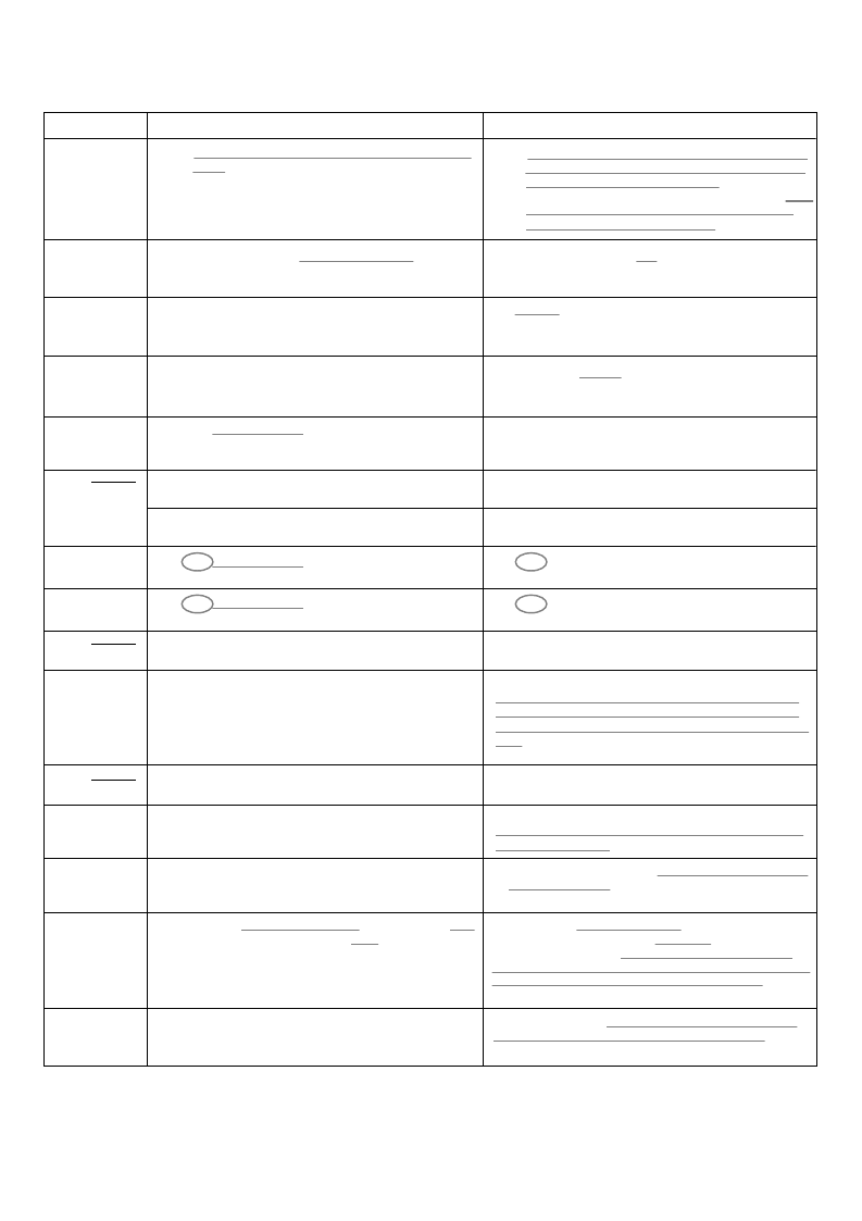
Corrections and
Page
Page 92,
Table 15,
Note
Supplement
ar
Erro
y
Explanation
r
for M37902FxC Dat
asheet (REV.
Correction
B) NO.9
(9/11)
No
t
e:
Be sur
MHz. f
fr
om pin X
I
e
(X
I
that syst
N
) m
N
(f
em clock f
sys
ean
s
the fr
X
IN
)
.
doe
ncy
s
of the input clock
not exceed 26
eque
No
t
e:
The PLL multipli
frequency of
the range f
frequency of
reset,
the PLL multipli
al
lowed to be changed only once.
cat
i
on r
output clock (
10 MHz to
the input clock fr
cation r
atio must
be set so
f
PLL
)
MHz. f
(X
I
om pin X
I
atio sel
that the
must be
N
) m
eans the
N
(f
X
IN
)
ect
bits are
the PLL
rom
i
n
26
. After
Page 98,
Right column,
Line 8
Page 98,
Right column,
Line 10
the ladder net
w
or
k of t
he
A
-
D
converter
wi
ll
the resistor ladder network of the A-D converter will
pin V
REF
to the ladder network, and the power dissipation
pin V
REF
to the resistor ladder network, and the power
dissipation
#
#
Page 96,
Left column,
Line 7
rest
the oscil
arted
lation circuit
a
nd
P
LL circuit
ha
ve
be
en
the oscil
lation circuit
h
as
be
en
restar
ted
#
M37902F8C
internal flash m
G
P
,
emory
M37902F
8CHP
: block configuration of
(Deleted)
#
Fi
guration of
g.
106. M
3
i
nt
7902FJCGP
ernal flash mem
,
M37902FJC
ory
HP :
b
lock confi-
Fig. 106. M37902FJCHP : block configuration of inter-
nal flash memory
Page 101,
Fig. 106
#
Fi
figuration of
g.
108. M
3
7902FCC
i
nt
ernal flash mem
G
P
,
M37902F
ory
CCHP
:
block con-
Fig. 107. M37902FCCHP : block configuration of inter-
nal flash memory
Page 102,
Fig. 107
#
M37902FE
of inter
CGP, M
fla
sh
37902
memor
FEC
HP :
b
lock conf
i
gurat
i
on
nal
y
(Deleted)
Fig. 110. M37902FGCGP, M37902FGCHP : block con-
figuration of internal flash memory
CGP,
M37902F
HCH
of inter
nal
fla
sh
memor
y
Fig. 108. M37902FGCHP : block configuration of inter-
nal flash memory
Page 102,
Fig. 108
#
M37902FH
P :
bl
ock
config
ur
ation
(Deleted)
#
Page 103,
Right column,
Lines 15 to 17
area if
Note that,
the user
when the boot ROM
use
s
the flash m
emory
area
se
read
r
ial
I/O
mode.
i
s
area if the user uses the flash memory serial I/O mode.
Addresses FFB0
16
to FFBF
16
are the reserved area for
the serial programmer. Therefore, when the user uses
the flash memory serial I/O mode, do not program to this
area.
Note that, when the boot ROM area is read
#
Page 106,
Right column,
After line 13
Page 106,
Fig. 114,
Notes 4
Page 107,
Left column,
Lines 16 to 20
progr
am the
u
ser
ROM
area.
program the user ROM area.
After reset removal, be sure not to change the status at
pins MD0 and MD1.
#
#
Pi
serial I/
n
co
nnection of
O mode
M37902F
xCGP in f
l
ash m
emory
(Deleted)
#
4:
V
alid onl
y
clear
to “0”
.
4:
Valid only clear to “0”. This bit 3 must be controll-
ed with bit 1 = “1”.
#
to an
address will
The write stat
command consists
e
ven
ad
dr
b
e
e
o
efore,
f
8-bit
u
nits
any data writt
must be
w
n
r
to an odd
i
t
ten only
ess; ther
i
nvalid.
e
even address;
address will
cycle of a
data m
ust be writt
The write stat
occu
be sure
no
command consisting of
therefor
b
e
i
nvalid. Sin
p
r
ogramm
8
bi
t
s must
mand written
the write data
command consists
en to even and odd addr
be written t
o an
e, any com
ce
ing
to an odd
at the 2nd
of 16 bits,
e
sses.
this
e
Page 107,
Right column,
After line 24
#
request
occu
r
rence.
request
r
rence.
to use
In the CPU
the
ST
reprogr
amming m
uction
od
e,
t
P
and
WIT
instr
s.
相關(guān)PDF資料 |
PDF描述 |
|---|---|
| M37905F8CFP | 16-BIT CMOS MICROCOMPUTER |
| M37905F8CSP | 16-BIT CMOS MICROCOMPUTER |
| M37905M4C | DIODE SCHOTTKY DUAL COMMON-ANODE 25V 200mW 0.32V-vf 200mA-IFM 1mA-IF 2uA-IR SOT-323 3K/REEL |
| M37905M4C-XXXFP | 16 BIT CMOS MICROCOMPUTER |
| M37905M4C-XXXSP | 16 BIT CMOS MICROCOMPUTER |
相關(guān)代理商/技術(shù)參數(shù) |
參數(shù)描述 |
|---|---|
| M37903S4CHP | 制造商:RENESAS 制造商全稱:Renesas Technology Corp 功能描述:16-BIT CMOS MICROCOMPUTER |
| M37905F8CFP | 制造商:MITSUBISHI 制造商全稱:Mitsubishi Electric Semiconductor 功能描述:16-BIT CMOS MICROCOMPUTER |
| M37905F8CSP | 制造商:MITSUBISHI 制造商全稱:Mitsubishi Electric Semiconductor 功能描述:16-BIT CMOS MICROCOMPUTER |
| M37905M4C | 制造商:MITSUBISHI 制造商全稱:Mitsubishi Electric Semiconductor 功能描述:16 BIT CMOS MICROCOMPUTER |
| M37905M4C-XXXFP | 制造商:MITSUBISHI 制造商全稱:Mitsubishi Electric Semiconductor 功能描述:16 BIT CMOS MICROCOMPUTER |
發(fā)布緊急采購(gòu),3分鐘左右您將得到回復(fù)。