- 您現(xiàn)在的位置:買賣IC網(wǎng) > PDF目錄201303 > BX80532KC2800D (INTEL CORP) 32-BIT, 2800 MHz, MICROPROCESSOR PDF資料下載
參數(shù)資料
| 型號: | BX80532KC2800D |
| 廠商: | INTEL CORP |
| 元件分類: | 微控制器/微處理器 |
| 英文描述: | 32-BIT, 2800 MHz, MICROPROCESSOR |
| 文件頁數(shù): | 14/129頁 |
| 文件大小: | 1640K |
| 代理商: | BX80532KC2800D |
第1頁第2頁第3頁第4頁第5頁第6頁第7頁第8頁第9頁第10頁第11頁第12頁第13頁當前第14頁第15頁第16頁第17頁第18頁第19頁第20頁第21頁第22頁第23頁第24頁第25頁第26頁第27頁第28頁第29頁第30頁第31頁第32頁第33頁第34頁第35頁第36頁第37頁第38頁第39頁第40頁第41頁第42頁第43頁第44頁第45頁第46頁第47頁第48頁第49頁第50頁第51頁第52頁第53頁第54頁第55頁第56頁第57頁第58頁第59頁第60頁第61頁第62頁第63頁第64頁第65頁第66頁第67頁第68頁第69頁第70頁第71頁第72頁第73頁第74頁第75頁第76頁第77頁第78頁第79頁第80頁第81頁第82頁第83頁第84頁第85頁第86頁第87頁第88頁第89頁第90頁第91頁第92頁第93頁第94頁第95頁第96頁第97頁第98頁第99頁第100頁第101頁第102頁第103頁第104頁第105頁第106頁第107頁第108頁第109頁第110頁第111頁第112頁第113頁第114頁第115頁第116頁第117頁第118頁第119頁第120頁第121頁第122頁第123頁第124頁第125頁第126頁第127頁第128頁第129頁
Intel Xeon Processor with 512 KB L2 Cache
110
Datasheet
All of the commands in Table 51 are for reading or writing registers in the SMBus thermal sensor,
except the one-shot command (OSHT) register. The one-shot command forces the immediate start
of a new conversion cycle. If a conversion is in progress when the one-shot command is received,
then the command is ignored. If the thermal sensor is in stand-by mode when the one-shot
command is received, a conversion is performed and the sensor returns to stand-by mode. The one-
shot command is not supported when the thermal sensor is in auto-convert mode.
Note:
Writing to a read-command register or reading from a write-command register will produce invalid
results.
The default command after reset is to a reserved value (00h). After reset, “Receive Byte” SMBus
packets will return invalid data until another command is sent to the thermal sensor.
7.4.6
SMBus Thermal Sensor Registers
7.4.6.1
Thermal Reference Registers
Once the SMBus thermal sensor reads the processor thermal diode, it performs an analog to digital
conversion and stores the result in the Thermal Reference Register (TRR). The supported range is
+127 to 0 decimal and is expressed as an eight-bit number representing temperature in degrees
Celsius. This eight-bit value consists of seven data bits and a sign bit (MSB) as shown in Table 52.
The values shown are also used to program the Thermal Limit Registers.
The values of these registers should be treated as saturating values. Values above 127 are
represented as 127 decimal, while values of zero and below may be represented as 0 to -127
decimal. If the thermal sensor returns a value with the sign bit set (1) and the data is 000_0000
through 111_1110, the temperature should be interpreted as 0 C.
7.4.6.2
Thermal Limit Registers
The SMBus thermal sensor has four Thermal Limit Registers: RRHL is used to read the high limit;
RRLL is read for the low limit; WRHL is used to write the high limit; and the WRLL to write the
low limit. These registers allow the user to define high and low limits for the processor core
thermal diode reading. The encoding for these registers is the same as for the Thermal Reference
Register shown in Table 52. If the processor thermal diode reading equals or exceeds one of these
limits, then the alarm bit (RHIGH or RLOW) in the Thermal Sensor Status Register is triggered.
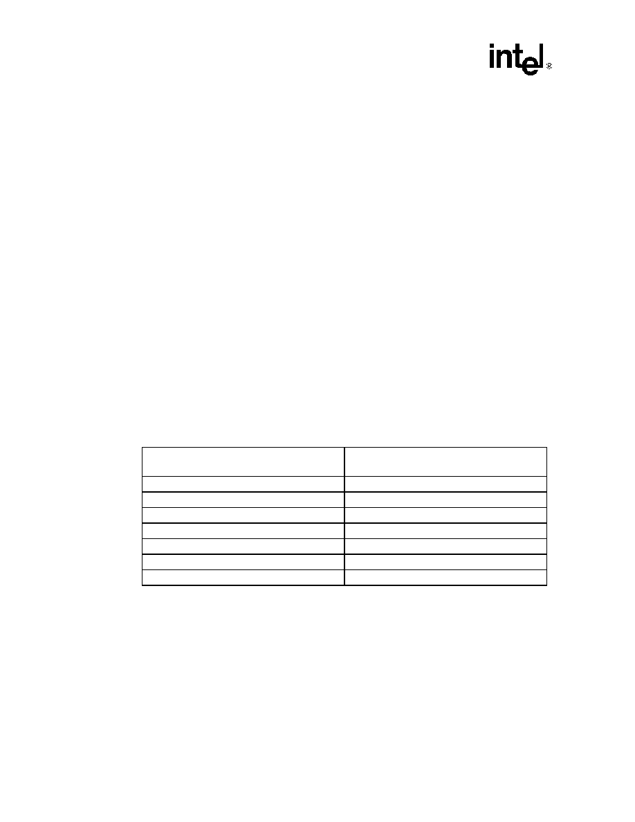
Table 52. Thermal Reference Register Values
Temperature
(°C)
Register Value
(binary)
+127
0 111 1111
+126
0 111 1110
+100
0 110 0100
+50
0 011 0010
+25
0 001 1001
+1
0 000 0001
0
0 000 0000
相關(guān)PDF資料 |
PDF描述 |
|---|---|
| BX80524R300128 | 32-BIT, 300 MHz, MICROPROCESSOR, XMA |
| BZV09/A0332/04 | 3A, 250VAC, FEMALE AND MALE, MAINS POWER CONNECTOR |
| BZV09/A0332/14 | 3A, 250VAC, FEMALE AND MALE, MAINS POWER CONNECTOR |
| BZV09/A0332/37 | 3A, 250VAC, FEMALE AND MALE, MAINS POWER CONNECTOR |
| BKT-146-01-F-V | 92 CONTACT(S), MALE, STRAIGHT TWO PART BOARD CONNECTOR, SURFACE MOUNT |
相關(guān)代理商/技術(shù)參數(shù) |
參數(shù)描述 |
|---|---|
| BX80532KC2800DU | 制造商:Intel 功能描述:MPU XEON PROCESSOR NETBURST 64-BIT 0.13UM 2.8GHZ - Boxed Product (Development Kits) |
| BX80532KC2800F | 制造商:Intel 功能描述:MPU XEON PROCESSOR NETBURST 64-BIT 0.13UM 2.8GHZ - Boxed Product (Development Kits) |
| BX80532KC3000D | 制造商:Intel 功能描述:MPU XEON PROCESSOR NETBURST 64-BIT 0.13UM 3GHZ - Boxed Product (Development Kits) |
| BX80532KC3000H | 制造商:Intel 功能描述:MPU XEON NETBURST 64-BIT 0.13UM 3GHZ - Boxed Product (Development Kits) |
| BX80532KE2000D | 制造商:Intel 功能描述:MPU XEON PROCESSOR NETBURST 64-BIT 0.13UM 2GHZ - Boxed Product (Development Kits) |
發(fā)布緊急采購,3分鐘左右您將得到回復(fù)。