- 您現(xiàn)在的位置:買賣IC網(wǎng) > PDF目錄231503 > WEDPNF8M721V-1012BC SPECIALTY MEMORY CIRCUIT, PBGA275 PDF資料下載
參數(shù)資料
| 型號(hào): | WEDPNF8M721V-1012BC |
| 元件分類: | 存儲(chǔ)器 |
| 英文描述: | SPECIALTY MEMORY CIRCUIT, PBGA275 |
| 封裝: | 32 X 25 MM, PLASTIC, BGA-275 |
| 文件頁數(shù): | 40/42頁 |
| 文件大小: | 686K |
| 代理商: | WEDPNF8M721V-1012BC |
第1頁第2頁第3頁第4頁第5頁第6頁第7頁第8頁第9頁第10頁第11頁第12頁第13頁第14頁第15頁第16頁第17頁第18頁第19頁第20頁第21頁第22頁第23頁第24頁第25頁第26頁第27頁第28頁第29頁第30頁第31頁第32頁第33頁第34頁第35頁第36頁第37頁第38頁第39頁當(dāng)前第40頁第41頁第42頁
7
White Electronic Designs Corporation (602) 437-1520 www.whiteedc.com
WEDPNF8M721V-XBX
SDRAM DESCRIPTION
The 64MByte (512Mb) SDRAM is a high-speed CMOS, dynamic
random-access ,memory using 5 chips containing 134, 217, 728
bits. Each chip is internally configured as a quad-bank DRAM with
a synchronous interface. Each of the chip’s 33,554,432-bit banks
is organized as 4,096 rows by 512 columns by 16 bits.
Read and write accesses to the SDRAM are burst oriented; ac-
cesses start at a selected location and continue for a programmed
number of locations in a programmed sequence. Accesses begin
with the registration of an ACTIVE command, which is then
followed by a READ or WRITE command. The address bits regis-
tered coincident with the ACTIVE command are used to select the
bank and row to be accessed (BA0, BA1 select the bank; A0-11
select the row). The address bits registered coincident with the
READ or WRITE command are used to select the starting column
location for the burst access.
The SDRAM provides for programmable READ or WRITE burst
lengths of 1, 2, 4 or 8 locations, or the full page, with a burst
terminate option. An AUTO PRECHARGE function may be enabled
to provide a self-timed row precharge that is initiated at the end
of the burst sequence.
The 64MB SDRAM uses an internal pipelined architecture to
achieve high-speed operation. This architecture is compatible
with the 2
n rule of prefetch architectures, but it also allows the
column address to be changed on every clock cycle to achieve a
high-speed, fully random access. Precharging one bank while
accessing one of the other three banks will hide the precharge
cycles and provide seamless, high-speed, random-access operation.
The 64MB SDRAM is designed to operate in 3.3V, low-power
memory systems. An auto refresh mode is provided, along with a
power-saving, power-down mode.
All inputs and outputs are LVTTL compatible. SDRAMs offer
substantial advances in DRAM operating performance, including
the ability to synchronously burst data at a high data rate with
automatic column-address generation, the ability to interleave
between internal banks in order to hide precharge time and the
capability to randomly change column addresses on each clock
cycle during a burst access.
SDRAM FUNCTIONAL DESCRIPTION
Read and write accesses to the SDRAM are burst oriented;
accesses start at a selected location and continue for a pro-
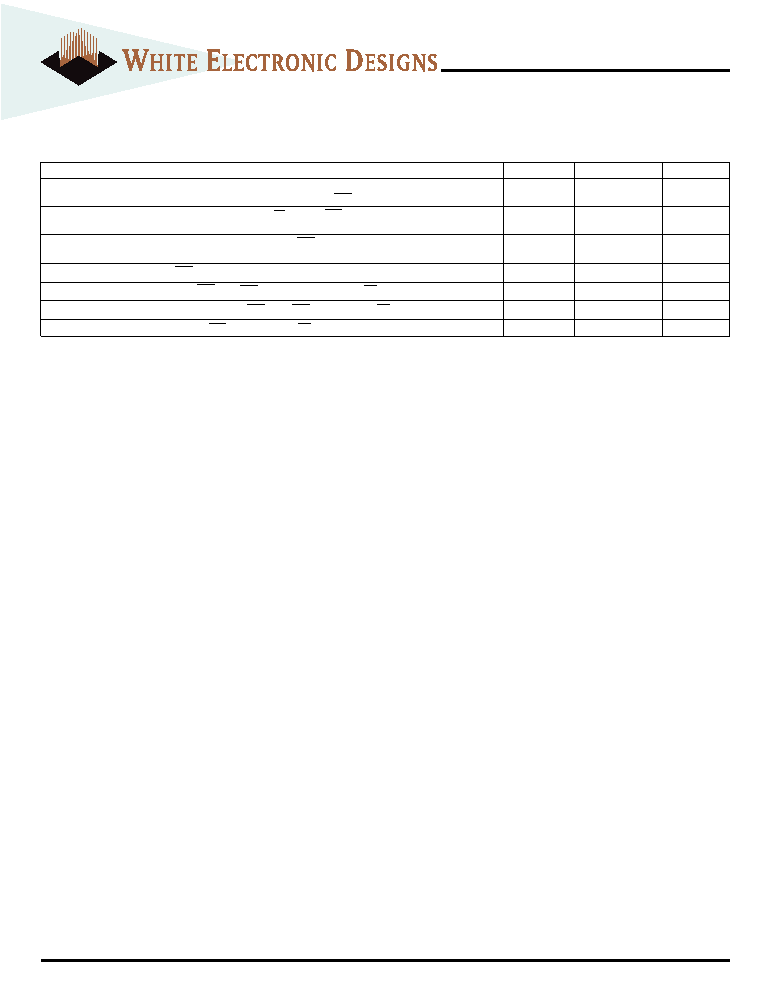
ICC SPECIFICATIONS AND CONDITIONS (Notes 1,2,3,4)
(VCC = +3.3V
±0.3V; TA = -55°C to +125°C)
Parameter/Condition
Symbol
Max
Units
SDRAM Operating Current: Active Mode;
ICC1
750
mA
Burst = 2; Read or Write; tRC = tRC (min); CAS latency = 3 (5, 6, 7); FCS = High
SDRAM Standby Current: Active Mode; CKE = HIGH; CS = HIGH; FCS = High;
ICC3
250
mA
All banks active after tRCD met; No accesses in progress (5, 7, 8)
SDRAM Operating Current: Burst Mode; Continuous burst; FCS = High
ICC4
750
mA
Read or Write; All banks active; CAS latency = 3 (5, 6, 7)
SDRAM Self Refresh Current; FCS = High (14)
ICC7
10
mA
Flash VCC Active Current for Read : FCS = VIL, FOE = VIH, f = 5MHz (9, 13); CS = CKE = High
IFCC1
40
mA
Flash VCC Active Current for Program or Erase: FCS = VIL, FOE = VIH (10, 13); CS = CKE = High
IFCC2
45
mA
Flash VCC Standby Current: VCC = 3.6, FCS = VIH, f = 5MHz; CS = CKE = High (13)
IFCC3
10
mA
NOTES:
1. All voltages referenced to VSS.
2. An initial pause of 100ms is required after power-up, followed by two
AUTO REFRESH commands, before proper device operation is ensured.
(VCC must be powered up simultaneously.) The two AUTO REFRESH
command wake-ups should be repeated any time the tREF refresh requirement
is exceeded.
3. AC timing and ICC tests have VIL = 0V and VIH = 3V, with timing referenced
to 1.5V crossover point.
4. ICC specifications are tested after the device is properly initialized.
5. ICC is dependent on output loading and cycle rates. Specified values are
obtained with minimum cycle time and the outputs open.
6. The ICC current will decrease as the CAS latency is reduced. This is due to
the fact that the maximum cycle rate is slower as the CAS latency is
reduced.
7. Address transitions average one transition every two clocks.
8. Other input signals are allowed to transition no more than once every two
clocks and are otherwise at valid VIH or VIL levels.
9. The ICC current listed includes both the DC operating current and the
frequency dependent component (at 5 MHz). The frequency component
typically is less than 8 mA/MHz, with OE at VIH.
10. ICC active while Embedded Algorithm (program or erase) is in progress.
11. Maximum ICC specifications are tested with VCC = VCC Max.
12. Automatic sleep mode enables the low power mode when addressed
remain stable for tacc + 30 ns.
13. SDRAM in self refresh mode
14. Self refresh available in commercial and industrial temperatures only.
相關(guān)PDF資料 |
PDF描述 |
|---|---|
| WE128K32-140G1UIA | 128K X 32 EEPROM 5V MODULE, 140 ns, CQFP68 |
| WE128K32-150G1UM | 128K X 32 EEPROM 5V MODULE, 150 ns, CQFP68 |
| WE128K32-200G1UMA | 128K X 32 EEPROM 5V MODULE, 200 ns, CQFP68 |
| WS128K32N-85HME | 512K X 8 MULTI DEVICE SRAM MODULE, 85 ns, CPGA66 |
| WSF512K16-72H2I | SPECIALTY MEMORY CIRCUIT, CPGA66 |
相關(guān)代理商/技術(shù)參數(shù) |
參數(shù)描述 |
|---|---|
| WEDPNF8M721V-1012BI | 制造商:未知廠家 制造商全稱:未知廠家 功能描述:8Mx72 Synchronous DRAM + 8Mb Flash Mixed Module Multi-Chip Package |
| WEDPNF8M721V-1012BM | 制造商:未知廠家 制造商全稱:未知廠家 功能描述:8Mx72 Synchronous DRAM + 8Mb Flash Mixed Module Multi-Chip Package |
| WEDPNF8M721V-1015BC | 制造商:未知廠家 制造商全稱:未知廠家 功能描述:8Mx72 Synchronous DRAM + 8Mb Flash Mixed Module Multi-Chip Package |
| WEDPNF8M721V-1015BI | 制造商:未知廠家 制造商全稱:未知廠家 功能描述:8Mx72 Synchronous DRAM + 8Mb Flash Mixed Module Multi-Chip Package |
| WEDPNF8M721V-1015BM | 制造商:未知廠家 制造商全稱:未知廠家 功能描述:8Mx72 Synchronous DRAM + 8Mb Flash Mixed Module Multi-Chip Package |
發(fā)布緊急采購,3分鐘左右您將得到回復(fù)。