- 您現(xiàn)在的位置:買賣IC網(wǎng) > PDF目錄383838 > ST20GP6 MAX 7000 CPLD 256 MC 208-RQFP PDF資料下載
參數(shù)資料
| 型號: | ST20GP6 |
| 英文描述: | MAX 7000 CPLD 256 MC 208-RQFP |
| 中文描述: | GPS處理器 |
| 文件頁數(shù): | 31/116頁 |
| 文件大小: | 1107K |
| 代理商: | ST20GP6 |
第1頁第2頁第3頁第4頁第5頁第6頁第7頁第8頁第9頁第10頁第11頁第12頁第13頁第14頁第15頁第16頁第17頁第18頁第19頁第20頁第21頁第22頁第23頁第24頁第25頁第26頁第27頁第28頁第29頁第30頁當(dāng)前第31頁第32頁第33頁第34頁第35頁第36頁第37頁第38頁第39頁第40頁第41頁第42頁第43頁第44頁第45頁第46頁第47頁第48頁第49頁第50頁第51頁第52頁第53頁第54頁第55頁第56頁第57頁第58頁第59頁第60頁第61頁第62頁第63頁第64頁第65頁第66頁第67頁第68頁第69頁第70頁第71頁第72頁第73頁第74頁第75頁第76頁第77頁第78頁第79頁第80頁第81頁第82頁第83頁第84頁第85頁第86頁第87頁第88頁第89頁第90頁第91頁第92頁第93頁第94頁第95頁第96頁第97頁第98頁第99頁第100頁第101頁第102頁第103頁第104頁第105頁第106頁第107頁第108頁第109頁第110頁第111頁第112頁第113頁第114頁第115頁第116頁
ST20-GP1
31/116
5.6
Interrupt configuration registers
The interrupt controller is allocated a 4k block of memory in the internal peripheral address space.
Information on interrupts is stored in registers as detailed in the following section. The registers can
be examined and set by the devlw (device load word) and devsw (device store word) instructions.
Note, they can not be accessed using memory instructions.
HandlerWptr register
The
HandlerWptr
registers (1 per interrupt) contain a pointer to the workspace of the interrupt
handler.
Note, before the interrupt is enabled, by writing a 1 in the
Mask
register, the user (or toolset) must
ensure that there is a valid
Wptr
in the register.
TriggerMode register
Each interrupt channel can be programmed to trigger on rising/falling edges or high/low levels on
the external
Interrupt
.
Note, level triggering is different to edge triggering in that if the input is held at the triggering level, a
continuous stream of interrupts is generated.
Mask register
An interrupt mask register is provided in the interrupt controller to selectively enable or disable
external interrupts. This mask register also includes a global interrupt disable bit to disable all
external interrupts whatever the state of the individual interrupt mask bits.
To complement this the interrupt controller also includes an interrupt pending register which
contains a pending flag for each interrupt channel. The
Mask
register performs a masking function
on the
Pending
register to give control over what is allowed to interrupt the CPU while retaining the
ability to continually monitor external interrupts.
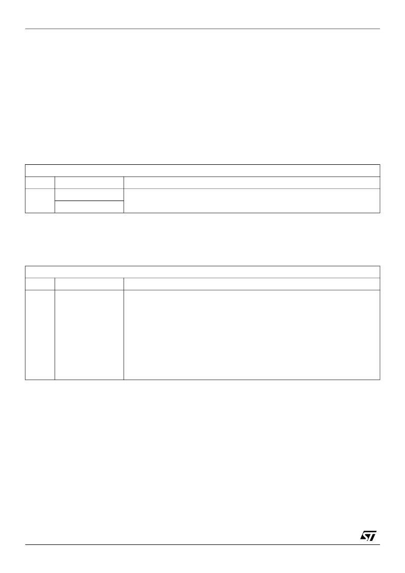
HandlerWptr0-4
Interrupt controller base address + #00 to #10
Read/Write
Bit
Bit field
Function
31:2
HandlerWptr
Pointer to the workspace of the interrupt handler.
1:0
RESERVED. Write 0.
Table 5.1
HandlerWptr
register format — one register per interrupt
TriggerMode0-4
Interrupt controller base address + #40 to #50
Read/Write
Bit
Bit field
Function
2:0
Trigger
Control the triggering condition of the
Interrupt
, as follows:
Trigger2:0
Interrupt triggers on
000
No trigger mode
001
High level - triggered while input high
010
Low level - triggered while input low
011
Rising edge - low to high transition
100
Falling edge - high to low transition
101
Any edge - triggered on rising and falling edges
110
No trigger mode
111
No trigger mode
Table 5.2
TriggerMode
register format — one register per interrupt
相關(guān)PDF資料 |
PDF描述 |
|---|---|
| ST25C02AB1 | IC FLEX 6000 FPGA 16K 144-TQFP |
| ST25C02AB6 | Stratix FPGA 25K FBGA-672 |
| ST25C02AM1 | IC ACEX 1K FPGA 100K 208-PQFP |
| ST25C02AM6 | Cyclone II FPGA 20K FBGA-256 |
| ST25C04ML1 | IC FLEX 6000 FPGA 24K 144-TQFP |
相關(guān)代理商/技術(shù)參數(shù) |
參數(shù)描述 |
|---|---|
| ST20-GP6 | 制造商:STMICROELECTRONICS 制造商全稱:STMicroelectronics 功能描述:GPS PROCESSOR |
| ST20GP6CT33S | 制造商:STMICROELECTRONICS 制造商全稱:STMicroelectronics 功能描述:GPS PROCESSOR |
| ST20GP6CX33S | 功能描述:射頻無線雜項(xiàng) GPS Processor RoHS:否 制造商:Texas Instruments 工作頻率:112 kHz to 205 kHz 電源電壓-最大:3.6 V 電源電壓-最小:3 V 電源電流:8 mA 最大功率耗散: 工作溫度范圍:- 40 C to + 110 C 封裝 / 箱體:VQFN-48 封裝:Reel |
| ST20GP6CX33STR | 功能描述:射頻無線雜項(xiàng) GPS Processor RoHS:否 制造商:Texas Instruments 工作頻率:112 kHz to 205 kHz 電源電壓-最大:3.6 V 電源電壓-最小:3 V 電源電流:8 mA 最大功率耗散: 工作溫度范圍:- 40 C to + 110 C 封裝 / 箱體:VQFN-48 封裝:Reel |
| ST20GP6X33S | 制造商:STMICROELECTRONICS 制造商全稱:STMicroelectronics 功能描述:GPS PROCESSOR |
發(fā)布緊急采購,3分鐘左右您將得到回復(fù)。