- 您現(xiàn)在的位置:買賣IC網(wǎng) > PDF目錄383995 > TE3-MUX (INFINEON TECHNOLOGIES AG) Ultraframer DS3/E3/DS2/E2/DS1/E1/DS0 PDF資料下載
參數(shù)資料
| 型號: | TE3-MUX |
| 廠商: | INFINEON TECHNOLOGIES AG |
| 元件分類: | 通信及網(wǎng)絡(luò) |
| 英文描述: | Ultraframer DS3/E3/DS2/E2/DS1/E1/DS0 |
| 中文描述: | Ultraframer DS3/E3/DS2/E2/DS1/E1/DS0 |
| 文件頁數(shù): | 40/211頁 |
| 文件大小: | 2567K |
| 代理商: | TE3-MUX |
第1頁第2頁第3頁第4頁第5頁第6頁第7頁第8頁第9頁第10頁第11頁第12頁第13頁第14頁第15頁第16頁第17頁第18頁第19頁第20頁第21頁第22頁第23頁第24頁第25頁第26頁第27頁第28頁第29頁第30頁第31頁第32頁第33頁第34頁第35頁第36頁第37頁第38頁第39頁當(dāng)前第40頁第41頁第42頁第43頁第44頁第45頁第46頁第47頁第48頁第49頁第50頁第51頁第52頁第53頁第54頁第55頁第56頁第57頁第58頁第59頁第60頁第61頁第62頁第63頁第64頁第65頁第66頁第67頁第68頁第69頁第70頁第71頁第72頁第73頁第74頁第75頁第76頁第77頁第78頁第79頁第80頁第81頁第82頁第83頁第84頁第85頁第86頁第87頁第88頁第89頁第90頁第91頁第92頁第93頁第94頁第95頁第96頁第97頁第98頁第99頁第100頁第101頁第102頁第103頁第104頁第105頁第106頁第107頁第108頁第109頁第110頁第111頁第112頁第113頁第114頁第115頁第116頁第117頁第118頁第119頁第120頁第121頁第122頁第123頁第124頁第125頁第126頁第127頁第128頁第129頁第130頁第131頁第132頁第133頁第134頁第135頁第136頁第137頁第138頁第139頁第140頁第141頁第142頁第143頁第144頁第145頁第146頁第147頁第148頁第149頁第150頁第151頁第152頁第153頁第154頁第155頁第156頁第157頁第158頁第159頁第160頁第161頁第162頁第163頁第164頁第165頁第166頁第167頁第168頁第169頁第170頁第171頁第172頁第173頁第174頁第175頁第176頁第177頁第178頁第179頁第180頁第181頁第182頁第183頁第184頁第185頁第186頁第187頁第188頁第189頁第190頁第191頁第192頁第193頁第194頁第195頁第196頁第197頁第198頁第199頁第200頁第201頁第202頁第203頁第204頁第205頁第206頁第207頁第208頁第209頁第210頁第211頁

PEB 3445 E
Functional Description
Data Sheet
40
2001-06-29
4.4
M12 Multiplexer/Demultiplexer and DS2 framer
The M12 multiplexer and the DS2 framer can be operated in two modes:
M12 multiplex format according to ANSI T1.107
ITU-T G.747 format
4.4.1
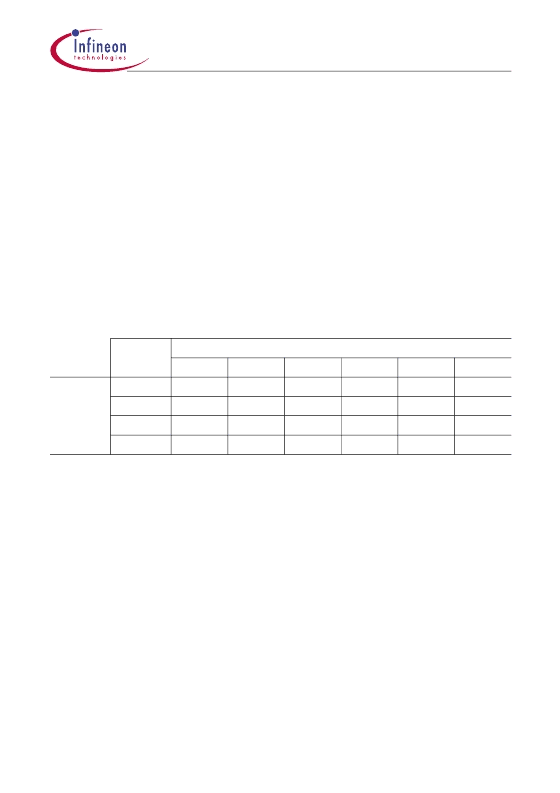
The framing structure of the M12 signal is shown in
Table 1
. A DS2 multiframe consists
of four subframes. Each subframe combines 6 blocks with 49 bits each. The first bit of
each block contains an overhead (OH) bit and 48 information bits. The 48 information
bits are formed by bit-by-bit interleaving of the four DS1 signals or a total of 12 bits from
each DS1 signal. The first bit is assigned to the 1
st
tributary DS1 signal, the second bit
is assigned to the 2
nd
tributary DS1 signal and so on.
M12 multiplex format
Table 1
M12 multiplex format
M
0
, M
1
M
0
and M
1
form the multiframe alignment signal. Each DS2 multiframe consists of three M-bits
and they are located in bit 0 of subframe one through three. The multiframe alignment signal is
’011’.
X
This bit is the fourth bit of the multiframe alignment signal and can be set to either ’0’ or ’1’. It is
accessible via an internal register.
F
0
, F
1
F
0
and F
1
form the frame alignment pattern. Each DS2 multiframe consists of eight F-bits, two
per subframe in block 3 and 6. F
0
and F
1
form the pattern ’01’. This pattern is repeated in every
subframe.
C
11
..C
43
The C-bits control the bit stuffing procedure of the multiplexed DS1 signals.
[48]
These bits represent a data block, which consists of 48 bits. [48] consists of four time slots of 12
bit and each time slot is assigned to one of four participating DS1 signals.
Subframe
Block 1 through 6 of a subframe
2
3
[48] C
11
[48]
F
0
[48] C
12
[48] C
13
[48]
[48] C
21
[48]
F
0
[48] C
22
[48] C
23
[48]
[48] C
31
[48]
F
0
[48] C
32
[48] C
33
[48]
[48] C
41
[48]
F
0
[48] C
42
[48] C
43
[48]
1
4
5
6
DS2-
Multiframe
1
2
3
4
M
0
M
1
M
1
X
F
1
F
1
F
1
F
1
[48]
[48]
[48]
[48]
相關(guān)PDF資料 |
PDF描述 |
|---|---|
| TEA1085 | Listening-in circuit for line-powered telephone sets |
| TEA1085A | Listening-in circuit for line-powered telephone sets |
| TEA1085AT | Listening-in circuit for line-powered telephone sets |
| TEA1085T | Listening-in circuit for line-powered telephone sets |
| TEA1093 | Hands-free IC |
相關(guān)代理商/技術(shù)參數(shù) |
參數(shù)描述 |
|---|---|
| TE3Q0TREB2201G | 制造商:Vishay Dale 功能描述:IND FLTR WW 2.2K UH 2% TRD - Bulk |
| TE3Q0TRPJ1000J | 制造商:Vishay Angstrohm 功能描述:Ind Filter Toroid 100uH 5% RDL Bulk 制造商:Vishay Dale 功能描述:IND FLTR WW 100UH 5% TRD - Bulk |
| TE3Q0TRPJ1100J | 制造商:Vishay Dale 功能描述:TE-3Q0TR 110 5% P09 - Bulk |
| TE3Q0TRPJ2201G | 制造商:Vishay Dale 功能描述:IND FLTR WW 2.2K UH 2% TRD - Bulk |
發(fā)布緊急采購,3分鐘左右您將得到回復(fù)。