- 您現(xiàn)在的位置:買賣IC網(wǎng) > PDF目錄384756 > MT48V16M16LFFG (Micron Technology, Inc.) MOBILE SDRAM PDF資料下載
參數(shù)資料
| 型號(hào): | MT48V16M16LFFG |
| 廠商: | Micron Technology, Inc. |
| 英文描述: | MOBILE SDRAM |
| 中文描述: | 移動(dòng)SDRAM |
| 文件頁數(shù): | 37/58頁 |
| 文件大小: | 1451K |
| 代理商: | MT48V16M16LFFG |
第1頁第2頁第3頁第4頁第5頁第6頁第7頁第8頁第9頁第10頁第11頁第12頁第13頁第14頁第15頁第16頁第17頁第18頁第19頁第20頁第21頁第22頁第23頁第24頁第25頁第26頁第27頁第28頁第29頁第30頁第31頁第32頁第33頁第34頁第35頁第36頁當(dāng)前第37頁第38頁第39頁第40頁第41頁第42頁第43頁第44頁第45頁第46頁第47頁第48頁第49頁第50頁第51頁第52頁第53頁第54頁第55頁第56頁第57頁第58頁

37
256Mb: x16 Mobile SDRAM
MobileRamY26L_A.p65 – Pub. 5/02
Micron Technology, Inc., reserves the right to change products or specifications without notice.
2002, Micron Technology, Inc.
256Mb: x16
MOBILE SDRAM
ADVANCE
17. Required clocks are specified by JEDEC function-
ality and are not dependent on any timing param-
eter.
18. The I
DD
current will increase or decrease propor-
tionally according to the amount of frequency al-
teration for the test condition.
19. Address transitions average one transition every
two clocks.
20. CLK must be toggled a minimum of two times dur-
ing this period.
21. Based on
t
CK = 7.5ns for -75,
t
CK=8ns for -8,
t
CK=10ns for -10 .
22. V
IH
overshoot: V
IH
(MAX) = V
DD
Q + 2V for a pulse
width
≤
3ns, and the pulse width cannot be greater
than one third of the cycle rate. V
IL
undershoot: V
IL
(MIN) = -2V for a pulse width
≤
1/3
t
CK.
23. The clock frequency must remain constant (stable
clock is defined as a signal cycling within timing
constraints specified for the clock pin) during ac-
cess or precharge states (READ, WRITE, including
t
WR, and PRECHARGE commands). CKE may be
used to reduce the data rate.
24. Auto precharge mode only. The precharge timing
budget (
t
RP) begins 7.5ns after the first clock de-
lay, after the last WRITE is executed. May not ex-
ceed limit set for precharge mode.
25. Precharge mode only.
26. JEDEC and PC100 specify three clocks.
27.
t
AC for -75 at CL = 3 with no load is 5.4ns and is
guaranteed by design.
28. Parameter guaranteed by design.
A.
Maximum capacitance can be 3.0 pF but not
desired.
B.
Maximum capacitance can be 5.0pF but not
desired.
C.
Maximum capacitance can be 3.3pF but not
desired.
D. Target values listed with alternative values in
parantheses.
E.
t
XSR must be less than or equal to
t
RC+1CLK
F.
For full I/V relationships see IBIS Section.
29. PC100 specifies a maximum of 4pF.
30. PC100 specifies a maximum of 5pF.
31. PC100 specifies a maximum of 6.5pF.
32. For -75, CL = 3 and
t
CK = 7.5ns; for -8, CL = 2 and
t
CK
= 10ns.
33. CKE is HIGH during refresh command period
t
RFC (MIN) else CKE is LOW. The I
DD
6 limit is actu-
ally a nominal value and does not result in a fail
value.
t
RFC must be less than or equal to
t
RC+1CLK
NOTES
1.
All voltages referenced to V
SS
.
2.
This parameter is sampled; f = 1 MHz, T
J
= 25°C;
0.9V bias, 200mV swing, V
DD
= +2.5V, V
DD
Q = +1.8V.
3.
I
DD
is dependent on output loading and cycle rates.
Specified values are obtained with minimum cycle
time and the outputs open.
4.
Enables on-chip refresh and address counters.
5.
The minimum specifications are used only to
indicate cycle time at which proper operation over
the full temperature range (0°C
≤
T
A
≤
+70°C and
- 40°C
≤
T
A
≤
+85°C for IT parts) is ensured.
6.
An initial pause of 100μs is required after power-
up, followed by two AUTO REFRESH commands,
before proper device operation is ensured. (V
DD
and V
DD
Q must be powered up simultaneously. V
SS
and V
SS
Q must be at same potential.) The two
AUTO REFRESH command wake-ups should be
repeated any time the
t
REF refresh requirement is
exceeded.
7.
AC characteristics assume
t
T = 1ns.
8.
In addition to meeting the transition rate specifi-
cation, the clock and CKE must transit between V
IH
and V
IL
(or between V
IL
and V
IH
) in a monotonic
manner.
9.
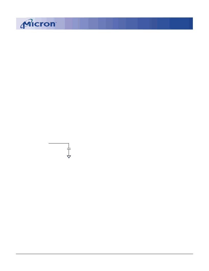
Outputs measured at 0.9V with equivalent load:
Q
30pF
10.
t
HZ defines the time at which the output achieves
the open circuit condition; it is not a reference to
V
OH
or V
OL
. The last valid data element will meet
t
OH before going High-Z.
11. AC timing and I
DD
tests have V
IL
= 0.0V and V
IH
1.65V,
with timing referenced to V
IH
/2 crossover point. If
the input transition time is longer than 1 ns, then
the timing is referenced at V
IL
(MAX) and V
IH
(MIN)
and no longer at the ISV crossover point.
12. Other input signals are allowed to transition no
more than once every two clocks and are otherwise
at valid V
IH
or V
IL
levels.
13. I
DD
specifications are tested after the device is prop-
erly initialized.
14. Timing actually specified by
t
CKS; clock(s) speci-
fied as a reference only at minimum cycle rate.
15. Timing actually specified by
t
WR plus
t
RP; clock(s)
specified as a reference only at minimum cycle rate.
16. Timing actually specified by
t
WR.
相關(guān)PDF資料 |
PDF描述 |
|---|---|
| MT48H16M16LFFG | MOBILE SDRAM |
| MT49H16M18C | 288Mb SIO REDUCED LATENCY(RLDRAM II) |
| MT49H16M18CFM-xx | 288Mb SIO REDUCED LATENCY(RLDRAM II) |
| MT49H32M9C | 288Mb SIO REDUCED LATENCY(RLDRAM II) |
| MT49H32M9CFM-xx | 288Mb SIO REDUCED LATENCY(RLDRAM II) |
相關(guān)代理商/技術(shù)參數(shù) |
參數(shù)描述 |
|---|---|
| MT48V16M32L2B5-8 IT | 制造商:Micron Technology Inc 功能描述:DRAM Chip Mobile SDRAM 512M-Bit 16Mx32 1.8V 90-Pin VFBGA Tray |
| MT48V16M32L2F5-8 IT | 制造商:Micron Technology Inc 功能描述:DRAM Chip Mobile SDRAM 512M-Bit 16Mx32 1.8V 90-Pin VFBGA Tray |
| MT48V32M16S2FG-10 | 制造商:Micron Technology Inc 功能描述:32MX16 SSDRAM PLASTIC 2BOC 2.5V - Trays |
| MT48V32M16S2FG-8 ES | 制造商:Micron Technology Inc 功能描述:DRAM CHIP MOBILE SDRAM 512MBIT 2.5V 54FBGA - Bulk |
發(fā)布緊急采購,3分鐘左右您將得到回復(fù)。