- 您現(xiàn)在的位置:買賣IC網(wǎng) > PDF目錄98005 > M34524MC-XXXFP 4-BIT, MROM, 6 MHz, MICROCONTROLLER, PQFP64 PDF資料下載
參數(shù)資料
| 型號(hào): | M34524MC-XXXFP |
| 元件分類: | 微控制器/微處理器 |
| 英文描述: | 4-BIT, MROM, 6 MHz, MICROCONTROLLER, PQFP64 |
| 封裝: | 14 X 14 MM, 0.80 MM PITCH, PLASTIC, QFP-64 |
| 文件頁數(shù): | 90/161頁 |
| 文件大?。?/td> | 1199K |
| 代理商: | M34524MC-XXXFP |
第1頁第2頁第3頁第4頁第5頁第6頁第7頁第8頁第9頁第10頁第11頁第12頁第13頁第14頁第15頁第16頁第17頁第18頁第19頁第20頁第21頁第22頁第23頁第24頁第25頁第26頁第27頁第28頁第29頁第30頁第31頁第32頁第33頁第34頁第35頁第36頁第37頁第38頁第39頁第40頁第41頁第42頁第43頁第44頁第45頁第46頁第47頁第48頁第49頁第50頁第51頁第52頁第53頁第54頁第55頁第56頁第57頁第58頁第59頁第60頁第61頁第62頁第63頁第64頁第65頁第66頁第67頁第68頁第69頁第70頁第71頁第72頁第73頁第74頁第75頁第76頁第77頁第78頁第79頁第80頁第81頁第82頁第83頁第84頁第85頁第86頁第87頁第88頁第89頁當(dāng)前第90頁第91頁第92頁第93頁第94頁第95頁第96頁第97頁第98頁第99頁第100頁第101頁第102頁第103頁第104頁第105頁第106頁第107頁第108頁第109頁第110頁第111頁第112頁第113頁第114頁第115頁第116頁第117頁第118頁第119頁第120頁第121頁第122頁第123頁第124頁第125頁第126頁第127頁第128頁第129頁第130頁第131頁第132頁第133頁第134頁第135頁第136頁第137頁第138頁第139頁第140頁第141頁第142頁第143頁第144頁第145頁第146頁第147頁第148頁第149頁第150頁第151頁第152頁第153頁第154頁第155頁第156頁第157頁第158頁第159頁第160頁第161頁
Rev.2.00
Jul 27, 2004
page 34 of 159
REJ03B0091-0200Z
4524 Group
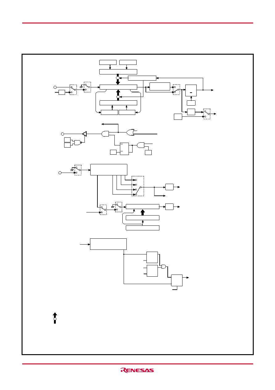
Fig. 26 Timer structure (2)
Register A
Reload control circuit
(TAB4)
W43
Q
R
T
(T4AB)
Timer 4 (8)
Register B
Reload register R4H (8)
(TAB4)
(T4AB)
PWMOD
(T4R4L)
T4F
ORCLK
XIN
1
W41
0
Timer 4,
Serial I/O
interrupt
1
W40
0
(T4HAB)
T3UDF
PWMOD
Port C output
Q
C/CNTR1
W31
W30
R
D
T
W32
W61
1
W52
0
Timer 5 (16)
1 - - 4 - - - - - - - -13 14 15 16
W51, W50
01
00
10
11
T5F
Timer 5
interrupt
Timer 5 underflow signal (T5UDF)
XCIN
1
W63
0
1/2
LCD clock
Reload register RLC (4)
Timer LC (4)
Register A
(TLCA)
1
W62
0
ORCLK
Watchdog
reset signal
Watchdog timer (16)
Q
S
Q
T
D
WDF2
Reset signal
R
Q
R
S
WEF
Reset signal
R
WDF1
WRST
instruction
INSTCK
+
DWDT instruction
WRST instruction
1 - - - - - - - - - - - - - - - - - - - 16
INSTCK :
ORCLK :
Instruction clock (system clock divided by 3)
Prescaler output (instruction clock divided by 1 to 256)
(Note 4)
(Note 5)
PWMOUT
(To timer 2 and timer 3)
0
W42
1
“H” interval
expansion
(Note 4)
(Note 6)
(Note 4)
(Note 8)
(Note 7)
1/2
Register A
Register B
Reload register R4L (8)
Data is set automatically from each reload
register when timer underflows
(auto-reload function).
Notes 4: Count source is stopped by clearing to “0.”
5: XIN cannot be used as count source when bit 1 (MR1) of register MR
is set to “1” and f(XIN) oscillation is stopped.
6: This timer is initialized (initial value = FFFF16) by stop of count
source (W52 = “0”).
7: Flag WDF1 is cleared to “0” and the next instruction is skipped when
the WRST instruction is executed while flag WDF1 = “1”.
The next instruction is not skipped even when the WRST instruction
is executed while flag WDF1 = “0”.
8: Flag WEF is cleared to “0” and watchdog timer reset does not occur
when the DWDT instruction and WRST instruction are executed
continuously.
9: The WEF flag is set to “1” at system reset or RAM back-up mode.
1
I30
0
SIOF
(From Serial I/O)
(Note 9)
相關(guān)PDF資料 |
PDF描述 |
|---|---|
| M34550E8FS | 4-BIT, UVPROM, 1.6 MHz, MICROCONTROLLER, CQCC80 |
| M34551E8-XXXFP | 4-BIT, OTPROM, MICROCONTROLLER, PQFP48 |
| M34554M8-XXXFP | 4-BIT, MROM, 6 MHz, MICROCONTROLLER, PQFP64 |
| M34554MC-XXXFP | 4-BIT, MROM, 6 MHz, MICROCONTROLLER, PQFP64 |
| M34571G6FP | 4-BIT, MROM, 6 MHz, MICROCONTROLLER, PDSO24 |
相關(guān)代理商/技術(shù)參數(shù) |
參數(shù)描述 |
|---|---|
| M3452-C09K1 | 制造商:Bonitron 功能描述:OVERVOLTAGE BRAKING TRANSISTOR |
| M3452-C125K2 | 制造商:Bonitron 功能描述:OVERVOLTAGE BRAKING TRANSISTOR |
| M3452-C125K2,A | 制造商:Bonitron 功能描述:OVERVOLTAGE BRAKING TRANSISTOR |
| M3452-C150B7 | 制造商:Bonitron 功能描述:OVERVOLTAGE BRAKING TRANSISTOR |
| M3452-C150B7-A | 制造商:Bonitron 功能描述:OVERVOLTAGE BRAKING TRANSISTOR |
發(fā)布緊急采購,3分鐘左右您將得到回復(fù)。