- 您現(xiàn)在的位置:買賣IC網(wǎng) > PDF目錄166397 > B900J24PXX12I 0-BIT, 80 MHz, OTHER DSP, PQFP44 PDF資料下載
參數(shù)資料
| 型號: | B900J24PXX12I |
| 元件分類: | 數(shù)字信號處理 |
| 英文描述: | 0-BIT, 80 MHz, OTHER DSP, PQFP44 |
| 文件頁數(shù): | 60/100頁 |
| 文件大小: | 1547K |
| 代理商: | B900J24PXX12I |
第1頁第2頁第3頁第4頁第5頁第6頁第7頁第8頁第9頁第10頁第11頁第12頁第13頁第14頁第15頁第16頁第17頁第18頁第19頁第20頁第21頁第22頁第23頁第24頁第25頁第26頁第27頁第28頁第29頁第30頁第31頁第32頁第33頁第34頁第35頁第36頁第37頁第38頁第39頁第40頁第41頁第42頁第43頁第44頁第45頁第46頁第47頁第48頁第49頁第50頁第51頁第52頁第53頁第54頁第55頁第56頁第57頁第58頁第59頁當(dāng)前第60頁第61頁第62頁第63頁第64頁第65頁第66頁第67頁第68頁第69頁第70頁第71頁第72頁第73頁第74頁第75頁第76頁第77頁第78頁第79頁第80頁第81頁第82頁第83頁第84頁第85頁第86頁第87頁第88頁第89頁第90頁第91頁第92頁第93頁第94頁第95頁第96頁第97頁第98頁第99頁第100頁
62
Lucent Technologies Inc.
B900
Advance Data Sheet
Baseband Signal Processor
July 1999
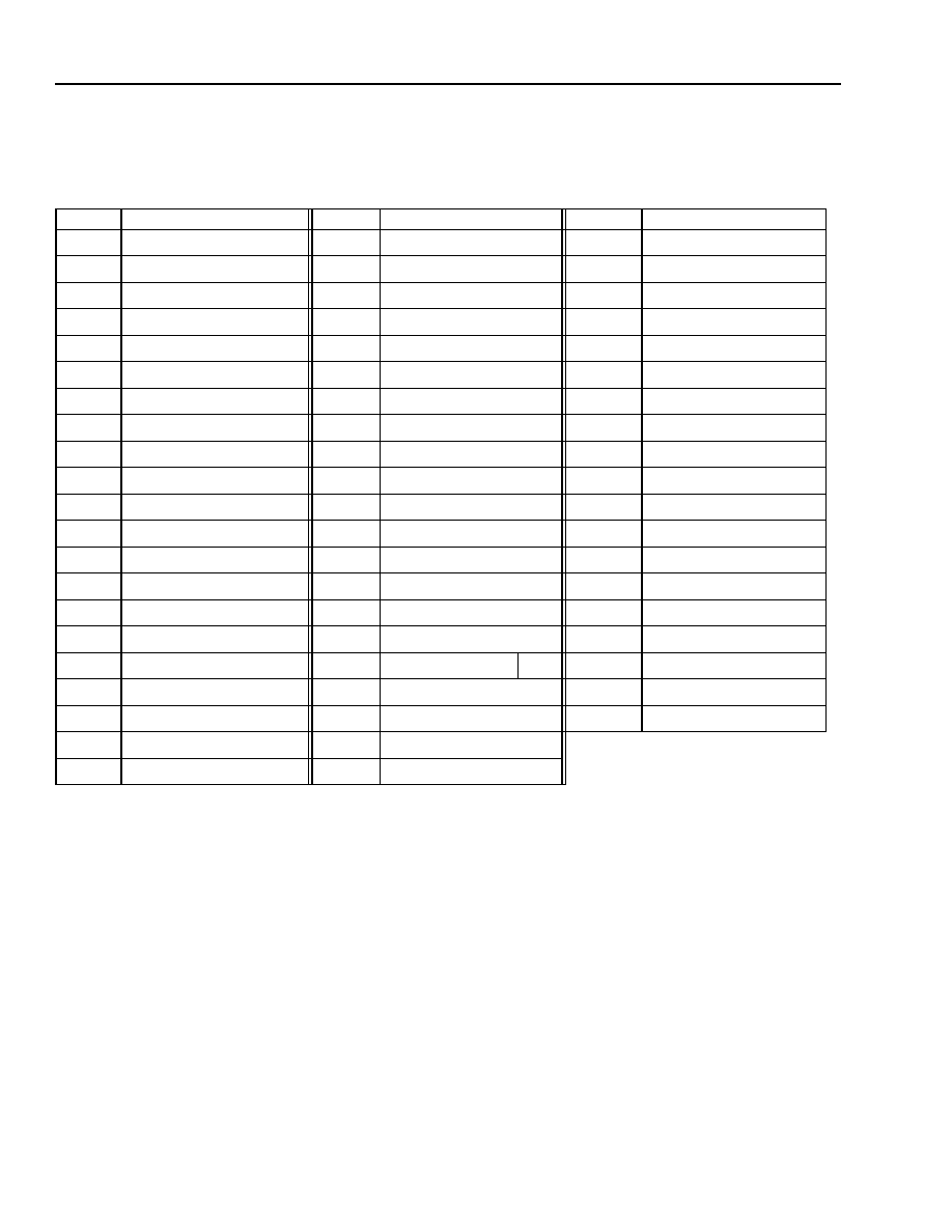
5 Software Architecture (continued)
5.3
Reset States
Table 54. Register States After Reset
Register
Bits 15—0
Register
Bits 15—0
Register
Bits 15—0
a0
IOPUCA*
* These registers are shown as upper-case because they are not directly program-accessible. They are accessed indirectly via write
operations to the cbit<a—d> registers.
CCCC CCCC CCCC CCCC
r3
a0l
IOPUCB* CCCC CCCC CCCC CCCC
rb
0000 0000 0000 0000
a1
IOPUCC* CCCC CCCC CCCC CCCC
re
0000 0000 0000 0000
a1l
IOPUCD* XXXX CCCC XXXX CCCC
sbita
0000 0000 PPPP PPPP
alf
00
inc
0000 0000 0000 0000
sbitb
0000 0000 PPPP PPPP
ar0
ins
Reset state for ins in B900 is 0110 0100 0101 0110.
0110 0000 0101 0100
sbitc
0000 0000 PPPP PPPP
ar1
i
sbitd
XXXX 0000 XXXX PPPP
ar2
j
sdx
ar3
jtag
sioc
0000 0000 0000 0000
auc
0000 0000 0000 0000
k
ssic
0100 0000 0000 0000
c0
p
ssid
c1
PC
0000 0000 0000 0000
timer0
0000 0000 0000 0000
c2
pi
SSSS SSSS SSSS SSSS
timer1
0000 0000 0000 0000
cbita
0000 0000
pl
timerc
0000 0000 0000 0000
cbitb
0000 0000
pllc
wdogr
cbitc
0000 0000
pr
x
cbitd
XXXX 0000 XXXX
psw
00
y
chipc
0000 0000 000C 000C
pt
ybase
chipo
CCCC
0CCC CCCC CCCC
r0
yl
clkc
0000 0000 0000 0000
r1
cloop
r2
Bit code: Indicates that this bit:
is unknown on powerup reset and unaffected by all other resets.
0
is set to logic zero by all types of resets.
1
is set to logic one by all types of resets.
C
is not affected by a pin (RSTB) reset or watchdog reset; however, powerup reset and JTAG reset clear
the bit to zero.
P
reflects the value on its corresponding input pin.
S
shadows the program counter (PC).
X
may not be written and is read as zero.
相關(guān)PDF資料 |
PDF描述 |
|---|---|
| B900J24FXX12IT | 0-BIT, 59.88 MHz, OTHER DSP, PQFP44 |
| BA00CC0WCP-V5 | 1A Low Dropout Voltage Regulator with Shut Down Switch(Adustable Voltage) |
| BA10E6 | COPPER ALLOY, TIN FINISH, RING TERMINAL |
| BA12004 | 0.5 A, 7 CHANNEL, NPN, Si, POWER TRANSISTOR |
| BA1518SUR5VP | SINGLE COLOR DISPLAY CLUSTER, ULTRA RED |
相關(guān)代理商/技術(shù)參數(shù) |
參數(shù)描述 |
|---|---|
| B-900-M-10 | 制造商:Thomas & Betts 功能描述: |
| B-900-M-10-EG | 制造商:Thomas & Betts 功能描述: |
| B-900-M-20 | 制造商:Thomas & Betts 功能描述: |
| B-900-M-20-EG | 制造商:Thomas & Betts 功能描述: |
| B901 | 制造商:EDAL 制造商全稱:EDAL 功能描述:Silicon Bridge Rectifier |
發(fā)布緊急采購,3分鐘左右您將得到回復(fù)。