- 您現(xiàn)在的位置:買賣IC網(wǎng) > PDF目錄384021 > TMS320AV110 (Texas Instruments, Inc.) MPEG Audio Decoder(MPEG音頻譯碼器) PDF資料下載
參數(shù)資料
| 型號: | TMS320AV110 |
| 廠商: | Texas Instruments, Inc. |
| 英文描述: | MPEG Audio Decoder(MPEG音頻譯碼器) |
| 中文描述: | MPEG音頻解碼器(的MPEG音頻譯碼器) |
| 文件頁數(shù): | 23/38頁 |
| 文件大小: | 796K |
| 代理商: | TMS320AV110 |
第1頁第2頁第3頁第4頁第5頁第6頁第7頁第8頁第9頁第10頁第11頁第12頁第13頁第14頁第15頁第16頁第17頁第18頁第19頁第20頁第21頁第22頁當(dāng)前第23頁第24頁第25頁第26頁第27頁第28頁第29頁第30頁第31頁第32頁第33頁第34頁第35頁第36頁第37頁第38頁
TMS320AV110
MPEG AUDIO DECODER
SCSS013C – MAY 1993 – REVISED AUGUST 1995
23
POST OFFICE BOX 655303
DALLAS, TEXAS 75265
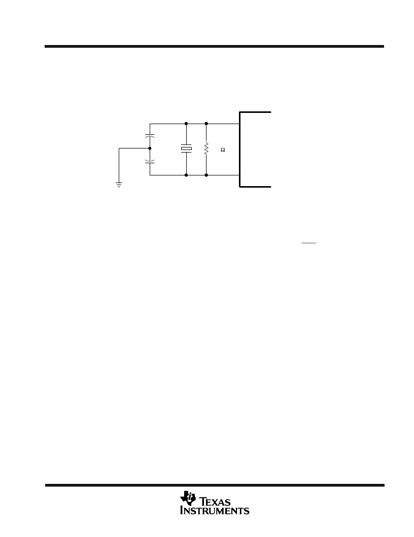
system clock
The system clock (OSCIN) can be totally asynchronous with respect to the other ’AV110 clocks and to the input
data rate. OSCIN can be driven from an oscillator as a clock input, or a crystal can be used to generate this clock.
If a crystal is used, it should be a fundamental-mode, parallel-resonant, 15-pF (typical) crystal connected to
OSCIN and OSCOUT. The crystal needs two 30-pF capacitors to ground and a 91-k
resistor across the crystal
as shown in Figure 14.
OSCIN
OSCOUT
30 pF
91 k
30 pF
Figure 14. Crystal Circuit
audio bypass
The ’AV110 has an audio-bypass feature that allows 16-bit PCM data to be loaded into the device and passed
through to the PCMDATA output. To use the audio-bypass feature, the STR_SEL register must be set to the
bypass mode and then a reset or restart sequence must be executed. Once the REQ output goes low, PCM
data can be loaded into the device directly. The data is loaded exactly the same as compressed data, using one
of the three loading mechanisms available. The data can be entered at up to the maximum burst rate. The rate
control features of the device can be used to check for buffer full and buffer empty. Blocks of 32 stereo samples
(32 16-bit words left, 32 16-bit words right) must be loaded with the data ordered as follows: 2 bytes left, 2 bytes
right, 2 bytes left, and so on. For each 2 bytes (left or right), the most significant byte is loaded first. If an
incomplete block is loaded at the end, the entire block will not be output. PCM data starts to output after 4 blocks
(512 bytes) have been loaded. The 18-bit PCM data is not supported for audio bypass.
To switch back to compressed data input, the STR_SEL register must be changed back to the proper input
configuration and then a reset or restart sequence must be executed. The PCM underflow interrupt can be used
to detect when all of the bypass data has been output.
decoding MPEG-2 streams
The ’AV110 accepts MPEG-2 frame data since it is the same as MPEG-1 frame data. In order for the ’AV110
to be able to accept MPEG-2 packet data, the MPEG-2 packets must be converted to MPEG-1 packets. The
difference is in the packet headers; the MPEG-2 packet header must be converted to a MPEG-1 packet header
that includes the PTS values. This allows the ’AV110 to extract the PTS values and present them at the
appropriate time.
相關(guān)PDF資料 |
PDF描述 |
|---|---|
| TMS320AV120 | MPEG Audio Decoder(MPEG音頻譯碼器) |
| TMS320AV220 | Video CD MPEG Decoder(視頻CD MPEG編碼器) |
| TMS320AV410 | Digital NTSC/PAL Encoder(數(shù)字NTSC/PAL編碼器) |
| TMS320AV411 | Digital NTSC/PAL Encoder(數(shù)字NTSC/PAL編碼器) |
| TMS320AV420 | Digital NTSC Encoder(數(shù)字NTSC編碼器) |
相關(guān)代理商/技術(shù)參數(shù) |
參數(shù)描述 |
|---|---|
| TMS320AV120 | 制造商:未知廠家 制造商全稱:未知廠家 功能描述:Digital Audio Decoder & Support |
| TMS320AV120FN | 制造商:未知廠家 制造商全稱:未知廠家 功能描述:Digital Audio Decoder & Support |
| TMS320AV220PCM | 制造商:未知廠家 制造商全稱:未知廠家 功能描述:Audio/Video Decoder for MPEG |
| TMS320AV410 | 制造商:未知廠家 制造商全稱:未知廠家 功能描述:Color Encoder Circuit |
| TMS320AV410PJM | 制造商:Rochester Electronics LLC 功能描述:- Bulk |
發(fā)布緊急采購,3分鐘左右您將得到回復(fù)。