- 您現(xiàn)在的位置:買賣IC網(wǎng) > PDF目錄384021 > TMS320AV110 (Texas Instruments, Inc.) MPEG Audio Decoder(MPEG音頻譯碼器) PDF資料下載
參數(shù)資料
| 型號: | TMS320AV110 |
| 廠商: | Texas Instruments, Inc. |
| 英文描述: | MPEG Audio Decoder(MPEG音頻譯碼器) |
| 中文描述: | MPEG音頻解碼器(的MPEG音頻譯碼器) |
| 文件頁數(shù): | 15/38頁 |
| 文件大小: | 796K |
| 代理商: | TMS320AV110 |
第1頁第2頁第3頁第4頁第5頁第6頁第7頁第8頁第9頁第10頁第11頁第12頁第13頁第14頁當(dāng)前第15頁第16頁第17頁第18頁第19頁第20頁第21頁第22頁第23頁第24頁第25頁第26頁第27頁第28頁第29頁第30頁第31頁第32頁第33頁第34頁第35頁第36頁第37頁第38頁
TMS320AV110
MPEG AUDIO DECODER
SCSS013C – MAY 1993 – REVISED AUGUST 1995
15
POST OFFICE BOX 655303
DALLAS, TEXAS 75265
resetting/initializing upon power up
Upon powering up the system, the host takes the following actions:
Resets the ’AV110 by using the RESET input. A few of the important actions that affect the user are:
–
REQ is high for the duration of the reset cycle.
–
The PCM output clocks are turned off and the PCMDATA out is zero.
–
Upon conclusion of the reset cycle, REQ goes low. The PCM output clocks and data remain zero.
The host must configure all ’AV110 control registers. The host can begin configuring the ’AV110 when RESET
is returned high. The host should set the PCM_DIV register before changing MUTE and PLAY. The host asserts
MUTE, which allows the PCM output clocks to start. Because PLAY is deasserted, PCMDATA out will be zero
(see Table 1). With MUTE asserted and PLAY deasserted, the host can begin supplying data and fill the pipe
while the D/A converter is initializing. After the required number of clocks to initialize the D/A, the host can assert
PLAY and deassert MUTE.
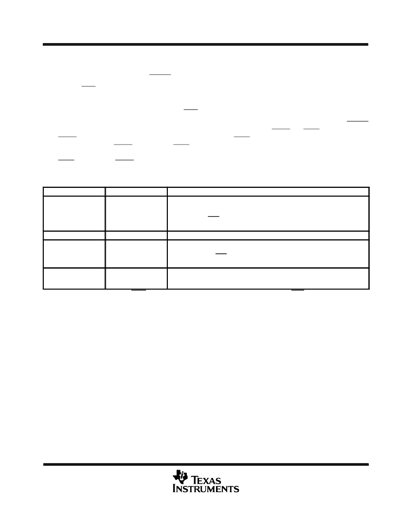
Table 1. Mute and Play Functional Summary
MUTE
PLAY
FUNCTION
Deasserted
Deasserted
Stops output clocks and PCMDATA output. LRCLK completes its current cycle and
stops. The SCLK completes the last cycle for the low period of the LRCLK and stops.
PCMDATA stops synchronous to LRCLK. Decoding stops when all internal buffers are
full. At this time, REQ goes high and the ’AV110 stops accepting data. When PLAY is
reasserted, PCMDATA output resumes where it left off, no data is lost.
Deasserted
Asserted
Normal decoding and playing
Asserted
Deasserted
Stops outputting data from PCM buffer; PCMDATA output is forced low synchronous to
LRCLK. SCLK and LRCLK are not stopped. Decoding stops when all internal buffers are
full. At this time, the REQ goes high and the ’AV110 stops accepting data. When PLAY
is reasserted, PCMDATA output resumes where it left off, no data is lost.
Asserted
Asserted
Decoding and muting (soft mute). The PCMDATA output gradually decays to zero. De-
coding continues as normal. When the PCMDATA output is low, PCM data is internally
consumed as if it were being output at PCMDATA.
NOTE: MUTE is asserted when either MUTE is low or the MUTE register is high. PLAY is asserted when both PLAY is low and the PLAY register
is high.
PCM output interface
The decoded audio data is output in a serial PCM data format. Output precision is selectable to be either
16 bits/word or 18 bits/word by setting the output precision select register (PCM_18). The data may be output
either with the most significant bit first or least significant bit first as selected by the contents of the output order
select register (PCM_ORD). When 18-bit data is selected, 24 bits of PCM data is output for each channel. The
data-in-front (DIF) register is used to select 18-bit data in front (at the beginning) or 18-bit data in the back (or
end) of the 24 bits (see Figure 8 through Figure 10).
The MPEG audio decoder requires a clock input (PCMCLK) that is externally synchronized to the compressed
audio bit stream. This clock can be at the actual PCMDATA output bit rate or it can be an integer multiple of the
bit rate. The decoder derives the PCM bit clock (SCLK) from this input (PCMCLK) by dividing it by the contents
of the divider value register (PCM_DIV). This value can be an integer from 1 to 32 and allows the use of
oversampling D/A converters. Values of SCLK and LRCLK are:
SCLK = (PCMCLK) / (PCM_DIV)
LRCLK = (SCLK) / (32); for 16-bit PCM output
LRCLK = (SCLK) / (48); for 18-bit PCM output
相關(guān)PDF資料 |
PDF描述 |
|---|---|
| TMS320AV120 | MPEG Audio Decoder(MPEG音頻譯碼器) |
| TMS320AV220 | Video CD MPEG Decoder(視頻CD MPEG編碼器) |
| TMS320AV410 | Digital NTSC/PAL Encoder(數(shù)字NTSC/PAL編碼器) |
| TMS320AV411 | Digital NTSC/PAL Encoder(數(shù)字NTSC/PAL編碼器) |
| TMS320AV420 | Digital NTSC Encoder(數(shù)字NTSC編碼器) |
相關(guān)代理商/技術(shù)參數(shù) |
參數(shù)描述 |
|---|---|
| TMS320AV120 | 制造商:未知廠家 制造商全稱:未知廠家 功能描述:Digital Audio Decoder & Support |
| TMS320AV120FN | 制造商:未知廠家 制造商全稱:未知廠家 功能描述:Digital Audio Decoder & Support |
| TMS320AV220PCM | 制造商:未知廠家 制造商全稱:未知廠家 功能描述:Audio/Video Decoder for MPEG |
| TMS320AV410 | 制造商:未知廠家 制造商全稱:未知廠家 功能描述:Color Encoder Circuit |
| TMS320AV410PJM | 制造商:Rochester Electronics LLC 功能描述:- Bulk |
發(fā)布緊急采購,3分鐘左右您將得到回復(fù)。