- 您現(xiàn)在的位置:買賣IC網(wǎng) > PDF目錄370584 > HIP8112A (Harris Corporation) NTSC/PAL Video Decoder PDF資料下載
參數(shù)資料
| 型號: | HIP8112A |
| 廠商: | Harris Corporation |
| 英文描述: | NTSC/PAL Video Decoder |
| 中文描述: | NTSC / PAL視頻解碼器 |
| 文件頁數(shù): | 23/40頁 |
| 文件大小: | 719K |
| 代理商: | HIP8112A |
第1頁第2頁第3頁第4頁第5頁第6頁第7頁第8頁第9頁第10頁第11頁第12頁第13頁第14頁第15頁第16頁第17頁第18頁第19頁第20頁第21頁第22頁當(dāng)前第23頁第24頁第25頁第26頁第27頁第28頁第29頁第30頁第31頁第32頁第33頁第34頁第35頁第36頁第37頁第38頁第39頁第40頁
4-23
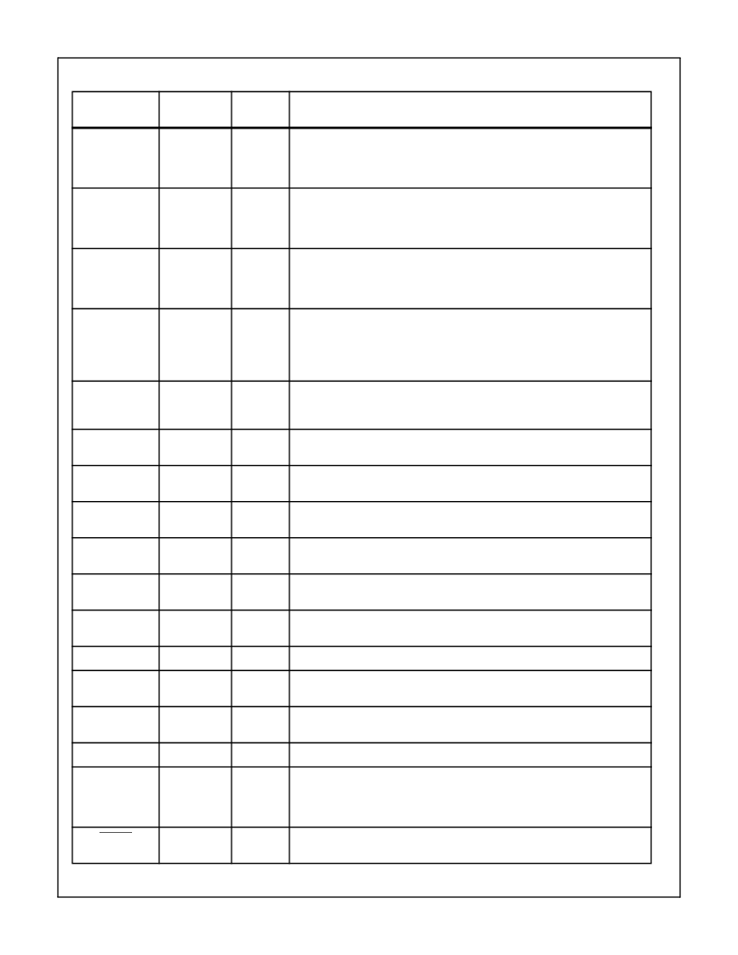
Pin Description
NAME
PQFP PIN
NUMBER
INPUT/
OUTPUT
DESCRIPTION
LIN0
7
Input
Composite video input. This input must be AC-coupled to the video signal using a
1.0
μ
F capacitor and terminated with a 75-ohm resistor. These components should
be as close to this pin as possible for best performance. If not used, this pin should
be connected to AGND thru a 0.1
μ
F capacitor.
LIN1
6
Input
Composite video input. This input must be AC-coupled to the video signal using a
1.0
μ
F capacitor and terminated with a 75-ohm resistor. These components should
be as close to this pin as possible for best performance. If not used, this pin should
be connected to AGND thru a 0.1
μ
F capacitor.
LIN2
5
Input
Composite video or Luminance (Y) video input. This input must be AC-coupled to the
video signal using a 1.0
μ
F capacitor and terminated with a 75-ohm resistor. These
components should be as close to this pin as possible for best performance. If not
used, this pin should be connected to AGND thru a 0.1
μ
F capacitor.
CIN
19
Input
Chrominance (C) video Input. This input must be AC-coupled to the video signal us-
ing a 1.0
μ
F capacitor and terminated with a 75-ohm resistor. These components,
and corresponding anti-aliasing low-pass filter, should be as close to this pin as pos-
sible for best performance. If not used, this pin should be connected to AGND thru a
0.1
μ
F capacitor.
WPE
27
Input
White Peak Enable. When enabled (‘1’), the video amplifiers gain is reduced when
the digital output code exceeds 248. When disabled (‘0’) the video amplifier will clip
when the A/D reaches code 255.
GAIN_CTRL
28
Input
Gain Control Input. DC voltage to set the S-Video CIN chrominance video amplifier’s
gain. Reference Figure 3 for gain control curve.
DEC_T
78
Input
Decoupling for upper A/D Converter Reference. Recommend connecting 0.1
μ
F and
0.01
μ
F ceramic capacitors in parallel to AGND.
DEC_L
30
Input
Decoupling for lower A/D Converter Reference. Recommend connecting 0.1
μ
F and
0.01
μ
F ceramic capacitors in parallel to AGND.
LAGC_CAP
77
Input
Capacitor Connection for Luminance AGC Circuit. Controls the AGC loop time con-
stant. Recommend connecting a 0.01
μ
F ceramic capacitor to AGND.
LCLAMP_CAP
76
Input
Capacitor Connection for Luminance Clamp Circuit. Controls the clamp loop time
constant. Recommend connecting a 0.047
μ
F ceramic capacitor to AGND.
CCLAMP_CAP
29
Input
Capacitor Connection for Chrominance Clamp Circuit. Controls the clamp loop time
constant. Recommend connecting a 0.047
μ
F ceramic capacitor to AGND.
L_ADIN
8
Input
Luminance A/D Converter input from external anti-alias filter. Reference Figure 1.
L_OUT
9
Output
Analog output of the video multiplexer. This output should connect to an external
anti-alias filter and return to L_ADIN input. Reference Figure 1.
SDA
40
Input/
Output
The serial I
2
C serial input/output data line.
SCL
41
Input
The serial I
2
C serial bus clock line.
CLK
13, 38
Input
Master clock for the decoder. This clock is used to run the internal logic, A/D convert-
ers, and Phase Locked Loops. All I/O pins (except the I
2
C) are synchronous to this
master clock. A ±50ppm crystal should be used with a waveform symmetry of
60/40% or better.
RESET
34
Input
Asynchronous Reset pin. Master Chip reset to initialize the internal states and set
the internal registers to a known state.
HMP8112A
相關(guān)PDF資料 |
PDF描述 |
|---|---|
| HIR19-21C | Technical Data Sheet 0.8mm Height Flat Top Infrared LED |
| HIR19-L11 | Technical Data Sheet 0.8mm Height Flat Top Infrared LED |
| HIR204C | 3mm Infrared LED, T-1 |
| HIR | 5mm Infrared LED, T-1 3/4 |
| HIR333 | 5mm Infrared LED, T-1 3/4 |
相關(guān)代理商/技術(shù)參數(shù) |
參數(shù)描述 |
|---|---|
| HIP-8V | 制造商:Belden Inc 功能描述:SPLITTER 8 WAY |
| HIP9010 | 制造商:INTERSIL 制造商全稱:Intersil Corporation 功能描述:Engine Knock Signal Processor |
| HIP9010AB | 制造商:Intersil Corporation 功能描述: |
| HIP9011 | 制造商:INTERSIL 制造商全稱:Intersil Corporation 功能描述:Engine Knock Signal Processor |
| HIP9011_06 | 制造商:INTERSIL 制造商全稱:Intersil Corporation 功能描述:Engine Knock Signal Processor |
發(fā)布緊急采購,3分鐘左右您將得到回復(fù)。