- 您現(xiàn)在的位置:買賣IC網(wǎng) > PDF目錄166397 > B900J24FXX12IT 0-BIT, 59.88 MHz, OTHER DSP, PQFP44 PDF資料下載
參數(shù)資料
| 型號(hào): | B900J24FXX12IT |
| 元件分類: | 數(shù)字信號(hào)處理 |
| 英文描述: | 0-BIT, 59.88 MHz, OTHER DSP, PQFP44 |
| 文件頁數(shù): | 26/100頁 |
| 文件大?。?/td> | 1547K |
| 代理商: | B900J24FXX12IT |
第1頁第2頁第3頁第4頁第5頁第6頁第7頁第8頁第9頁第10頁第11頁第12頁第13頁第14頁第15頁第16頁第17頁第18頁第19頁第20頁第21頁第22頁第23頁第24頁第25頁當(dāng)前第26頁第27頁第28頁第29頁第30頁第31頁第32頁第33頁第34頁第35頁第36頁第37頁第38頁第39頁第40頁第41頁第42頁第43頁第44頁第45頁第46頁第47頁第48頁第49頁第50頁第51頁第52頁第53頁第54頁第55頁第56頁第57頁第58頁第59頁第60頁第61頁第62頁第63頁第64頁第65頁第66頁第67頁第68頁第69頁第70頁第71頁第72頁第73頁第74頁第75頁第76頁第77頁第78頁第79頁第80頁第81頁第82頁第83頁第84頁第85頁第86頁第87頁第88頁第89頁第90頁第91頁第92頁第93頁第94頁第95頁第96頁第97頁第98頁第99頁第100頁
Lucent Technologies Inc.
31
Advance Data Sheet
B900
July 1999
Baseband Signal Processor
4 Hardware Architecture (continued)
4.7
I/O Ports (IOP)
The B900 contains three 8-bit IOP units and one 4-bit IOP unit, IOP<A—D>. Each IOP controls the directions of
eight bidirectional control I/O pins, IOP<A—D>[7:0]. If a pin is configured as an output, it can be individually set,
cleared, or toggled. If a pin is configured as an input, it can be read. See Table 18 for IOP operation.
4.7.1 IOP Operation
The lower half of each sbit<a—d> register (see Table 38 on page 50) contains the current value (VALUE[7:0]) of
that register’s eight bidirectional pins. The upper half of each sbit<a—d> register (DIR[7:0]) controls the direction
of each pin independently. A logic 1 configures the corresponding pin as an output; a logic 0 configures it as an
input. Reset clears the upper half of each sbit<a—d>, configuring all IOP<A—D> pins as inputs.
The cbit<a—d> registers (see Table 38 on page 50) each contain two 8-bit fields, MODE[7:0] and DATA[7:0]. Reset
clears the values of MODE[7:0]. The meaning of a bit in either field depends on whether it has been configured as
an input or an output in the corresponding sbit<a—d> register. If a pin has been configured to be an output, the
meanings are MODE and DATA. For an input, MODE and DATA are used on some pins as multiplex controls, or for
IOPA interrupt control. Table 18 shows the functionality of the MODE and DATA bits based on the direction selected
for the associated IOP pin.
If an IOP pin is switched from being configured as an output to being configured as an input and then back to being
configured as an output, the pin retains the previous output value.
IO pull-up registers (iopuc<a—d>) are enabled by setting bit 5 of the chipc register (see Table 39 on page 51).
Refer to Table 44 on page 55 for the use of these registers.
4.7.2 IOPA Interrupt Circuitry
The IOPA port has an interrupt generation capability to help perform functions like a keypad scan. Each IOPA bit
can individually be configured to generate the IOPA interrupt or not. To configure a bit for interrupt, it should be set
as an input, with its mode bit set to 1. For example, to configure IOPA[1] for interrupt, set (cbita[9] = 1) and (sbita[9]
= 0).
The interrupt generation logic compares the current state of the IOPA pins against a shadowed state which is
loaded with the IOPA pins every time the sbita register is read. Whenever the current state and the shadowed state
differ, an interrupt is generated. Which IOPA pin caused the interrupt can be determined by reading the sbita regis-
ter. Reading sbita is also necessary to clear the interrupt and reload the shadowed state. Before any pins are
enabled for interrupt, sbita should be read once to set the initial shadowed state to a defined value.
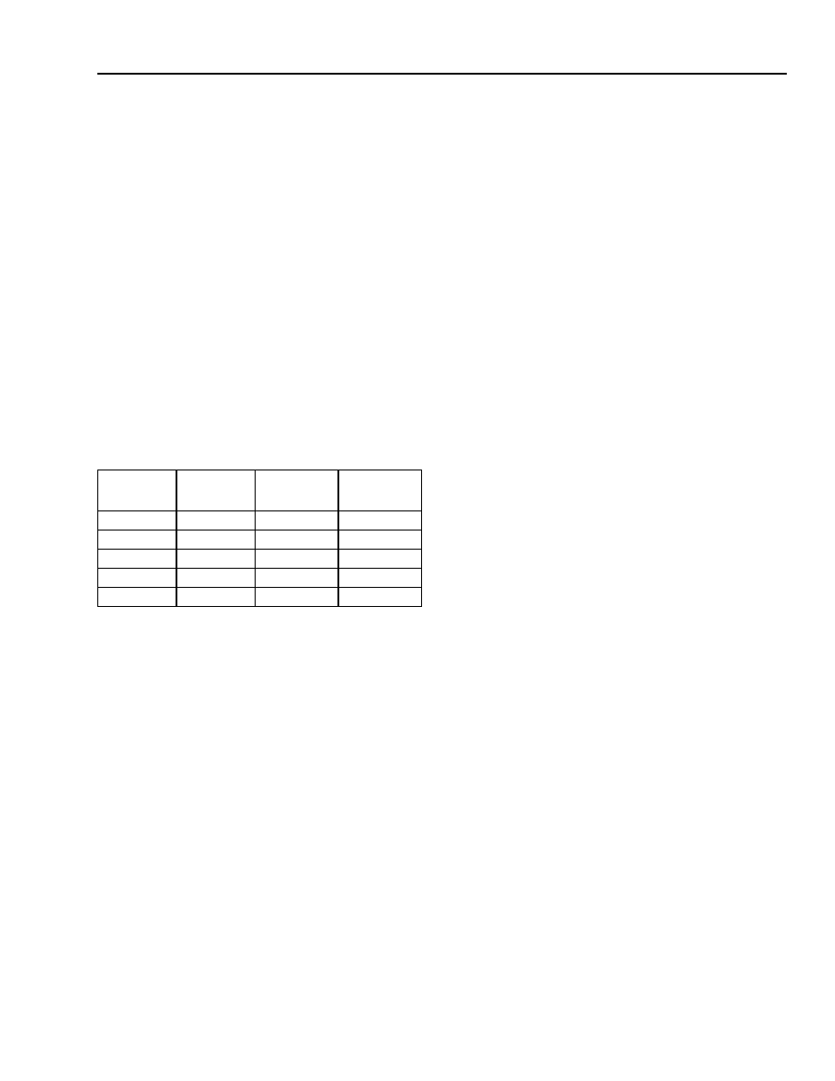
Table 18. IOP Operation
DIR[n*]
* For IOP<A—C>: 0
≤ n ≤ 7; for IOPD: 0 ≤ n ≤ 3.
Action on
IOP[n*]
1 (Output)
0
Clear
1 (Output)
0
1
Set
1 (Output)
1
0
No Change
1 (Output)
1
Toggle
0 (Input)
Don’t Care
Input
相關(guān)PDF資料 |
PDF描述 |
|---|---|
| BA00CC0WCP-V5 | 1A Low Dropout Voltage Regulator with Shut Down Switch(Adustable Voltage) |
| BA10E6 | COPPER ALLOY, TIN FINISH, RING TERMINAL |
| BA12004 | 0.5 A, 7 CHANNEL, NPN, Si, POWER TRANSISTOR |
| BA1518SUR5VP | SINGLE COLOR DISPLAY CLUSTER, ULTRA RED |
| BA1524LUR5VP | SINGLE COLOR DISPLAY CLUSTER, ULTRA RED |
相關(guān)代理商/技術(shù)參數(shù) |
參數(shù)描述 |
|---|---|
| B-900-M-10 | 制造商:Thomas & Betts 功能描述: |
| B-900-M-10-EG | 制造商:Thomas & Betts 功能描述: |
| B-900-M-20 | 制造商:Thomas & Betts 功能描述: |
| B-900-M-20-EG | 制造商:Thomas & Betts 功能描述: |
| B901 | 制造商:EDAL 制造商全稱:EDAL 功能描述:Silicon Bridge Rectifier |
發(fā)布緊急采購,3分鐘左右您將得到回復(fù)。