- 您現(xiàn)在的位置:買賣IC網(wǎng) > PDF目錄374046 > ADV7162KS220 (ANALOG DEVICES INC) 96-Bit, 220 MHz True-Color Video RAM-DAC PDF資料下載
參數(shù)資料
| 型號: | ADV7162KS220 |
| 廠商: | ANALOG DEVICES INC |
| 元件分類: | 顯示控制器 |
| 英文描述: | 96-Bit, 220 MHz True-Color Video RAM-DAC |
| 中文描述: | 1600 X 1200 PIXELS PALETTE-DAC DSPL CTLR, PQFP160 |
| 封裝: | PLASTIC, QFP-160 |
| 文件頁數(shù): | 19/44頁 |
| 文件大小: | 668K |
| 代理商: | ADV7162KS220 |
第1頁第2頁第3頁第4頁第5頁第6頁第7頁第8頁第9頁第10頁第11頁第12頁第13頁第14頁第15頁第16頁第17頁第18頁當(dāng)前第19頁第20頁第21頁第22頁第23頁第24頁第25頁第26頁第27頁第28頁第29頁第30頁第31頁第32頁第33頁第34頁第35頁第36頁第37頁第38頁第39頁第40頁第41頁第42頁第43頁第44頁
ADV7160/ADV7162
REV. 0
–19–
COLOR VIDEO MODES
The ADV7160/ADV7162 supports a number of color video
modes all at the maximum video rate.
Command bits CR27–CR24 of Command Register 2 along with
bit MR11 of Mode Register 1 determine the color mode. Seven
color modes use the Color Palette, and three of them bypass the
palette and control the DACs directly.
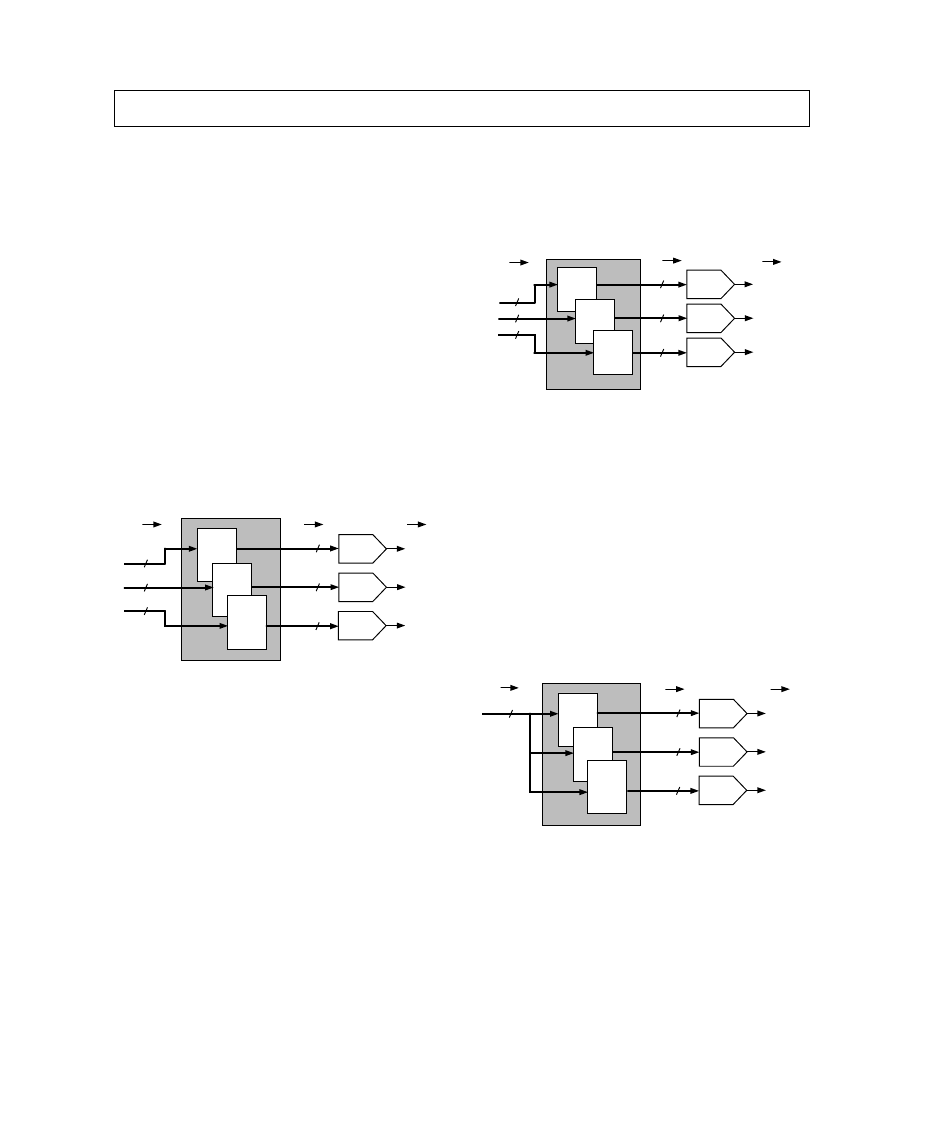
24-Bit True Color
(CR27, CR26, CR25, CR24 = 1, 1, 1, 0)
The part is set to 24-bit/30-bit “Gamma” True-Color operation
with MR11 set to Logic “1” and direct 24-bit True-Color op-
eration with MR11 set to Logic “0.” The pixel port accepts 24
bits of color data which is directly mapped to the Look-Up
Table RAM. With MR11 set to Logic “1,” the Look-Up Table
is configured as a 256 location by 30 bits deep RAM (10 bits
each for Red, Green and Blue), the RAM is preloaded with a
user determined, nonlinear function, such as a gamma correc-
tion curve and the output of the RAM drives the DACs with
30-bit data. With MR11 set to Logic “0,” the Look-Up Table is
configured as a 256 location by 24 bits deep RAM (8 bits each
for Red, Green and Blue), the RAM is preloaded with a linear
function and the output of the RAM drives the DACs with 24-
bit data.
8
8
8
24-BIT COLOR
DATA
24-BIT TO 30-BIT
LOOK-UP TABLE
30-BIT COLOR
DATA
ANALOG VIDEO
OUTPUTS
RED
256 x 10
10
10
10
10-BIT
RED
DAC
10-BIT
GREEN
DAC
10-BIT
BLUE
DAC
RED
OUT
GREEN
OUT
BLUE
OUT
GREEN
256 x 10
BLUE
256 x 10
Figure 23. 24-Bit to 30-Bit True-Color Configuration
16-Bit True Color
(CR27, CR26, CR25, CR24 = 1, 0, 1, 1)
The part is set to 16-bit True-Color operation. The pixel port
accepts 16 bits of color data which is mapped to the 5 LSBs of
each of the red and blue palettes of the Look-Up-Table RAM,
and 6 LSBs of the green palette of the Look-Up-Table RAM.
With MR11 set to Logic “1,” the Look-Up Table is configured
as a 64 location by 30 bits deep RAM (10 bits each for Red,
Green and Blue) and the output of the RAM drives the DACs
with 30-Bit data, allowing the display of 16-bit Gamma-
Corrected True-Color Images. With MR11 set to Logic “0,”
the Look-Up Table is configured as a 64 location by 24 bits
deep RAM (8 bits each for Red, Green and Blue); and the out-
put of the RAM drives the DACs with 24-bit data, allowing the
display of 16-bit True-Color Images.
15-Bit True Color
(CR27, CR26, CR25, CR24 = 1, 1, 0, 0 or 1, 1, 0, 1)
The part is set to 15-bit True-Color operation. The pixel port
accepts 15 bits of color data which is mapped to the 5 LSBs of
each of the red, green and blue palettes of the Look-Up Table
RAM. With MR11 set to Logic “1,” the Look-Up Table is con-
figured as a 32 location by 30 bits deep RAM (10 bits each for
Red, Green and Blue) and the output of the RAM drives the
DACs with 30-bit data, allowing the display of 15-bit Gamma-
Corrected True-Color Images. With MR11 set to Logic “0,”
the Look-Up Table is configured as a 32 location by 24 bits
deep RAM (8 bits each for Red, Green and Blue) and the out-
put of the RAM drives the DACs with 24-bit data, allowing the
display of 15-bit True-Color Images.
15-BIT COLOR
DATA
15-BIT TO 24-BIT
LOOK-UP TABLE
ANALOG VIDEO
OUTPUTS
RED
32 x 8
GREEN
32 x 8
BLUE
32 x 8
5
5
5
8
8
8
8-BIT
RED
DAC
8-BIT
GREEN
DAC
8-BIT
BLUE
DAC
RED
OUT
GREEN
OUT
BLUE
OUT
24-BIT COLOR
DATA
Figure 24. 15-Bit to 24-Bit True-Color Configuration
8-Bit Pseudo Color
(CR27, CR26, CR25, CR24 = 0, 0, 0, 0 or 0, 1, 0, 0 or 1, 0, 0, 0)
This mode sets the part into 8-bit Pseudo-Color operation. The
pixel port accepts 8 bits of pixel data, from either the red, blue
or green channel. With MR11 set to Logic “1,” a 30-bit word is
indexed in the Look-Up Table RAM. The Look-Up Table is
configured as a 256 location by 30 bits deep RAM (10 bits each
for Red, Green and Blue). The output of the RAM drives the
DACs with 30-bit data. With MR11 set to Logic “0,” a 24-Bit
word is indexed in the Look-Up Table RAM. The Look-Up
Table is configured as a 256 location by 24 bits deep RAM (8
bits each for Red, Green and Blue). The output of the RAM
drives the DACs with 24-bit data. This mode allows for the dis-
play of 256 simultaneous colors out of a total palette of millions
of addressable colors.
8-BIT PIXEL
DATA
8-BIT TO 30-BIT
LOOK-UP TABLE
30-BIT COLOR
DATA
ANALOG VIDEO
OUTPUTS
RED
256 x 10
10
10
10
10-BIT
RED
DAC
10-BIT
GREEN
DAC
10-BIT
BLUE
DAC
RED
OUT
GREEN
OUT
BLUE
OUT
8
GREEN
256 x 10
BLUE
256 x 10
Figure 25. 8-Bit to 30-Bit Pseudo-Color Configuration
PIXEL PORT MAPPING
The pixel data to the ADV7160/ADV7162 is automatically
mapped in the parts pixel port as determined by the pixel data
mode programmed (Bits CR27–CR24 of Command Register 2).
Pixel data in the 24-bit True-Color modes is directly mapped to
the 24 color inputs R7–R0, G7–G0 and B7–B0.
There is one mode of operation for 16-bit True Color. Data is
input to the device over the red and green color ports (R7–R0
and G7–G0) and is internally mapped to LUT Locations 0–63
according to Figure 26. (Note: Data on unused pixel inputs is
ignored.)
.
相關(guān)PDF資料 |
PDF描述 |
|---|---|
| ADV7160KS140 | 96-Bit, 220 MHz True-Color Video RAM-DAC |
| ADV7160KS170 | 96-Bit, 220 MHz True-Color Video RAM-DAC |
| ADV7160KS220 | 96-Bit, 220 MHz True-Color Video RAM-DAC |
| ADV7170 | Digital PAL/NTSC Video Encoder with 10-Bit SSAF⑩ and Advanced Power Management |
| ADV7170KS | Digital PAL/NTSC Video Encoder with 10-Bit SSAF⑩ and Advanced Power Management |
相關(guān)代理商/技術(shù)參數(shù) |
參數(shù)描述 |
|---|---|
| ADV7162KSZ140 | 制造商:Analog Devices 功能描述:DAC 3-CH Segment 10-bit 160-Pin MQFP |
| ADV7162KSZ220 | 制造商:Analog Devices 功能描述:DAC 3-CH Segment 10-bit 160-Pin MQFP |
| ADV7170 | 制造商:AD 制造商全稱:Analog Devices 功能描述:Digital PAL/NTSC Video Encoder with 10-Bit SSAF⑩ and Advanced Power Management |
| ADV71707911 | 制造商:LG Corporation 功能描述:FRAME ASSEMBLY |
| ADV7170KS | 制造商:AD 制造商全稱:Analog Devices 功能描述:Digital PAL/NTSC Video Encoder with 10-Bit SSAF⑩ and Advanced Power Management |
發(fā)布緊急采購,3分鐘左右您將得到回復(fù)。