- 您現(xiàn)在的位置:買(mǎi)賣(mài)IC網(wǎng) > PDF目錄375384 > AX88196BLF (ASIX Electronics Corporation) Low-pin-count Non-PCI 8/16-bit 10/100M Fast Ethernet Controller with MII Interface PDF資料下載
參數(shù)資料
| 型號(hào): | AX88196BLF |
| 廠商: | ASIX Electronics Corporation |
| 英文描述: | Low-pin-count Non-PCI 8/16-bit 10/100M Fast Ethernet Controller with MII Interface |
| 中文描述: | 低引腳數(shù)不符合信息產(chǎn)業(yè)部的PCI接口16位產(chǎn)品個(gè)10/100M快速以太網(wǎng)控制器 |
| 文件頁(yè)數(shù): | 17/86頁(yè) |
| 文件大小: | 551K |
| 代理商: | AX88196BLF |
第1頁(yè)第2頁(yè)第3頁(yè)第4頁(yè)第5頁(yè)第6頁(yè)第7頁(yè)第8頁(yè)第9頁(yè)第10頁(yè)第11頁(yè)第12頁(yè)第13頁(yè)第14頁(yè)第15頁(yè)第16頁(yè)當(dāng)前第17頁(yè)第18頁(yè)第19頁(yè)第20頁(yè)第21頁(yè)第22頁(yè)第23頁(yè)第24頁(yè)第25頁(yè)第26頁(yè)第27頁(yè)第28頁(yè)第29頁(yè)第30頁(yè)第31頁(yè)第32頁(yè)第33頁(yè)第34頁(yè)第35頁(yè)第36頁(yè)第37頁(yè)第38頁(yè)第39頁(yè)第40頁(yè)第41頁(yè)第42頁(yè)第43頁(yè)第44頁(yè)第45頁(yè)第46頁(yè)第47頁(yè)第48頁(yè)第49頁(yè)第50頁(yè)第51頁(yè)第52頁(yè)第53頁(yè)第54頁(yè)第55頁(yè)第56頁(yè)第57頁(yè)第58頁(yè)第59頁(yè)第60頁(yè)第61頁(yè)第62頁(yè)第63頁(yè)第64頁(yè)第65頁(yè)第66頁(yè)第67頁(yè)第68頁(yè)第69頁(yè)第70頁(yè)第71頁(yè)第72頁(yè)第73頁(yè)第74頁(yè)第75頁(yè)第76頁(yè)第77頁(yè)第78頁(yè)第79頁(yè)第80頁(yè)第81頁(yè)第82頁(yè)第83頁(yè)第84頁(yè)第85頁(yè)第86頁(yè)
ASIX ELECTRONICS CORPORATION
17
AX88196BLF
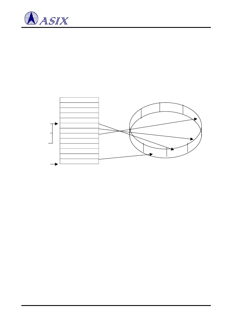
Initialization Of The Buffer Ring
Two static registers and two working registers control the operation of the Buffer Ring. These are the Page Start
Register, Page Stop Register (both described previously), the Current Page Register and the Boundary Pointer
Register. The Current Page Register points to the first buffer used to store a packet and is used to restore the DMA
for writing status to the Buffer Ring or for restoring the DMA address in the event of a Runt packet, a CRC, or
Frame Alignment error. The Boundary Register points to the first packet in the Ring not yet read by the host. If the
local DMA address ever reaches the Boundary, reception is aborted. The Boundary Pointer is also used to initialize
the Remote DMA for removing a packet and is advanced when a packet is removed. A simple analogy to remember
the function of these registers is that the Current Page Register acts as a Write Pointer and the Boundary Pointer acts
as a Read Pointer.
Buffer #1
Buffer #2
Buffer #3
…
…
…
…
Buffer #n
Physical Memory Map
Logic Receive Buffer Ring
Fig - 5 Receive Buffer Ring At Initialization
Beginning Of Reception
When the first packet begins arriving the AX88196B and begins storing the packet at the location pointed to by the
Current Page Register. An offset of 4 bytes is reserved in this first buffer to allow room for storing receives status
corresponding to this packet.
Linking Receive Buffer Pages
If the length of the packet exhausts the first 256 bytes buffer, the DMA performs a forward link to the next buffer to
store the remainder of the packet. For a maximal length packet the buffer logic will link six buffers to store the entire
packet. Buffers cannot be skipped when linking; a packet will always be stored in contiguous buffers. Before the
next buffer can be linked, the Buffer Management Logic performs two comparisons. The first comparison tests for
equality between the DMA address of the next buffer and the contents of the Page Stop Register. If the buffer
address equals the Page Stop Register, the buffer management logic will restore the DMA to the first buffer in the
Receive Buffer Ring value programmed in the Page Start Address Register. The second of comparison test between
the DMA address of the next buffer address and the contents of the Boundary Pointer Register. If the two values are
equal the reception is aborted. The Boundary Pointer Register can be used to protect against overwriting any area in
the receive buffer that has not yet been read. When linking buffers, buffer management will never cross this pointer,
effectively avoiding any overwrites. If the buffer address does not match either the Boundary Pointer or Page Stop
Address, the link to the next buffer is performed.
4000h
8000h
Page Start
Page Stop
1
2
3
4
…
n-2
n-1
n
Boundary Page
Current Page
相關(guān)PDF資料 |
PDF描述 |
|---|---|
| AX88658AB | 8-Port 10/100/1000BASE-T Ethernet Switch |
| AX88772_07 | USB to 10/100 Fast Ethernet/HomePNA Controller |
| AX88772 | USB to 10/100 Fast Ethernet/HomePNA Controller |
| AX88780_07 | IC,D/A CONVERTER,MC144110DW, 6-BIT,5-15V,SOIC-20,3-7US SER. |
| AX88780 | High-Performance Non-PCI Single-Chip 32-bit 10/100M Fast Ethernet Controller |
相關(guān)代理商/技術(shù)參數(shù) |
參數(shù)描述 |
|---|---|
| AX88196L | 制造商:未知廠家 制造商全稱(chēng):未知廠家 功能描述:10/100BASE 3-in-1 Local CPU Bus Fast Ethernet Controller with Embedded SRAM |
| AX88613 | 制造商:ASIX 制造商全稱(chēng):ASIX 功能描述:ASIX Multi-Port Ethernet Controller |
| AX88615 | 制造商:未知廠家 制造商全稱(chēng):未知廠家 功能描述:5-Port 10/100BASE Ethernet Switch |
| AX88615P | 制造商:未知廠家 制造商全稱(chēng):未知廠家 功能描述:5-Port 10/100BASE Ethernet Switch |
| AX8863T | 制造商:MAXIM 制造商全稱(chēng):Maxim Integrated Products 功能描述:Low-Dropout, 120mA Linear Regulators |
發(fā)布緊急采購(gòu),3分鐘左右您將得到回復(fù)。