- 您現(xiàn)在的位置:買賣IC網(wǎng) > PDF目錄98305 > TVP5041PFP (TEXAS INSTRUMENTS INC) COLOR SIGNAL DECODER, PQFP80 PDF資料下載
參數(shù)資料
| 型號(hào): | TVP5041PFP |
| 廠商: | TEXAS INSTRUMENTS INC |
| 元件分類: | 顏色信號(hào)轉(zhuǎn)換 |
| 英文描述: | COLOR SIGNAL DECODER, PQFP80 |
| 封裝: | POWER, PLASTIC, TQFP-80 |
| 文件頁數(shù): | 13/106頁 |
| 文件大?。?/td> | 501K |
| 代理商: | TVP5041PFP |
第1頁第2頁第3頁第4頁第5頁第6頁第7頁第8頁第9頁第10頁第11頁第12頁當(dāng)前第13頁第14頁第15頁第16頁第17頁第18頁第19頁第20頁第21頁第22頁第23頁第24頁第25頁第26頁第27頁第28頁第29頁第30頁第31頁第32頁第33頁第34頁第35頁第36頁第37頁第38頁第39頁第40頁第41頁第42頁第43頁第44頁第45頁第46頁第47頁第48頁第49頁第50頁第51頁第52頁第53頁第54頁第55頁第56頁第57頁第58頁第59頁第60頁第61頁第62頁第63頁第64頁第65頁第66頁第67頁第68頁第69頁第70頁第71頁第72頁第73頁第74頁第75頁第76頁第77頁第78頁第79頁第80頁第81頁第82頁第83頁第84頁第85頁第86頁第87頁第88頁第89頁第90頁第91頁第92頁第93頁第94頁第95頁第96頁第97頁第98頁第99頁第100頁第101頁第102頁第103頁第104頁第105頁第106頁
1–6
1.7
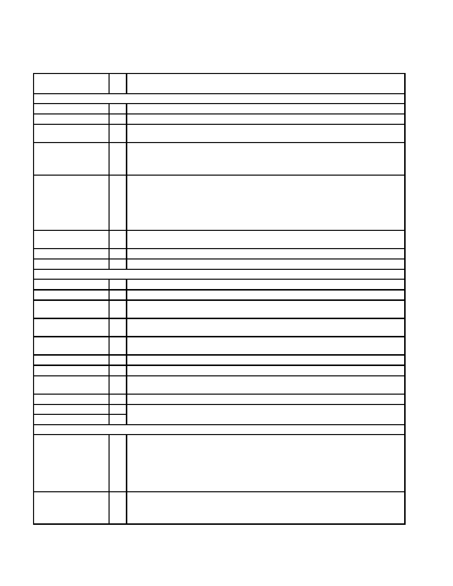
Terminal Functions (Continued)
TERMINAL
I/O
DESCRIPTION
NAME
NO.
I/O
DESCRIPTION
Miscellaneous Signals
RSTOUTB
22
O
Reset output, active low
RSTINB
23
I
Reset input, active low
OEB
24
I/O
Output enable for Y and UV terminals. Output enable is also controllable via the host port. When this terminal
is a logic 1, it forces Y and UV output terminals to high impedance states (active low).
GLCO
31
I/O
This serial output carries color PLL information. A slave device can decode the information to allow chroma
frequency control to the TVP5041. Data is transmitted at the SCLK rate. Additionally, this terminal, in
conjunction with PALI and FID, is used to determine the host port mode configuration during initial power
up.
GPCL
38
I/O
General-purpose control logic. This terminal has three functions:
1) General-purpose output. In this mode the state of GPCL is directly programmed via the host port.
2) Vertical blank output. In this mode the GPCL terminal is used to indicate the vertical blanking interval
of the output video. The beginning and end times of this signal are programmable via the host port
control.
3) Sync lock control input. In this mode when GPCL is high, the output clock frequencies and the sync timing
are forced to nominal values.
CLAMP1,
CLAMP2
2,
13
O
Clamp voltage outputs. Connect a 0.1-
F decoupling capacitor from each terminal to analog ground
NC
14, 15
No connection
BG
1
O
Connect a 1-
F capacitor from this terminal to CH1_AGND – CH2_AGND
Power Supplies
AFE_VDD
18
Analog supply. Connect to 3.3-V analog supply
AFE_GND
16
Analog ground
CH1_AGND
CH2_AGND
3
12
Analog grounds
CH1_AVDD
CH2_AVDD
6
9
Analog supply. Connect to 3.3-V analog supply.
DGND
21, 37, 47,
57, 68
Digital grounds
PLL_AGND
20
PLL ground. Connect to analog ground.
PLL_AVDD
19
Pll supply. Connect to 3.3-V analog supply.
DVDD
34, 44, 54,
65, 75
Digital supply. Connect to 3.3-V.
NSUB
17
Susbstrate ground. Connect to analog ground.
REFP
8
O
A/D reference supply. Connect a 4.7-
F capacitor from each terminal to analog ground. Connect a 1-F
REFM
7
O
capacitor across REFM and REFP terminals.
Sync Signals
AVID
28
I/O
Active video indicator. This signal is high during the horizontal active time of the video output on the Y and
UV terminals. AVID continues to toggle during vertical blanking intervals.
This terminal may be placed in a high-impedance state. During reset, AVID is an input, used to program the
behavior of Y[9:0], UV[9:0], HSYN, VSYN, AVID, and FID immediately after the completion of reset. If AVID
is pulled up during reset, Y[9:0], UV[9:0], HSYN, VSYN, AVID, PALI, and FID actively drive after reset. If
AVID is pulled down during reset, Y[9:0], UV[9:0], HSYN, VSYN, AVID, PALI, and FID remain in
high-impedance state after reset.
FID
33
I/O
Odd/even field indicator or vertical lock indicator. For odd/even indicator, a logic 1 indicates the odd field.
For vertical lock indicator, a logic 1 indicates the internal vertical PLL is in a locked state. Additionally, this
terminal in conjunction with GLCO and PALI is used to determine the host port configuration during initial
power up and reset.
相關(guān)PDF資料 |
PDF描述 |
|---|---|
| TVP5146M1PFP | COLOR SIGNAL DECODER, PQFP80 |
| TVP5146M2IPFPR | COLOR SIGNAL DECODER, PQFP80 |
| TVP5146M2IPFP | COLOR SIGNAL DECODER, PQFP80 |
| TVP5146M2PFPR | COLOR SIGNAL DECODER, PQFP80 |
| TVP5146M2PFP | COLOR SIGNAL DECODER, PQFP80 |
相關(guān)代理商/技術(shù)參數(shù) |
參數(shù)描述 |
|---|---|
| TVP5145 | 制造商:未知廠家 制造商全稱:未知廠家 功能描述:NTSC/PAL/SECAM/Component Digital Video Decoder With Macrovision(TM) Detection |
| TVP5145EVM | 制造商:Texas Instruments 功能描述:TVP5145EVM - Bulk |
| TVP5145PFP | 功能描述:視頻 IC NTSC/PAL/SECAM/ Comp Dig Vid Dec RoHS:否 制造商:Fairchild Semiconductor 工作電源電壓:5 V 電源電流:80 mA 最大工作溫度:+ 85 C 封裝 / 箱體:TSSOP-28 封裝:Reel |
| TVP5146 | 制造商:TI 制造商全稱:Texas Instruments 功能描述:NTSC/PAL / SECAM 4 X 10 BIT DIGITAL VIDEO DECODER WITH MACROVISION DETECTION YPBPR/RGB INPUTS 5 LINE COMB FILTER AND SCART SUPPORT |
| TVP5146_12 | 制造商:TI 制造商全稱:Texas Instruments 功能描述:NTSC/PAL/SECAM 4x10-Bit Digital Video Decoder With Macrovision?£a Detection, YPbPr/RGB Inputs, 5-Line Comb Filter, and SCART Support |
發(fā)布緊急采購,3分鐘左右您將得到回復(fù)。