- 您現(xiàn)在的位置:買(mǎi)賣(mài)IC網(wǎng) > PDF目錄370849 > M37902FGCGP (Mitsubishi Electric Corporation) SINGLE-CHIP 16-BIT CMOS MICROCOMPUTER PDF資料下載
參數(shù)資料
| 型號(hào): | M37902FGCGP |
| 廠商: | Mitsubishi Electric Corporation |
| 英文描述: | SINGLE-CHIP 16-BIT CMOS MICROCOMPUTER |
| 中文描述: | 單片16位CMOS微機(jī) |
| 文件頁(yè)數(shù): | 48/143頁(yè) |
| 文件大小: | 1463K |
| 代理商: | M37902FGCGP |
第1頁(yè)第2頁(yè)第3頁(yè)第4頁(yè)第5頁(yè)第6頁(yè)第7頁(yè)第8頁(yè)第9頁(yè)第10頁(yè)第11頁(yè)第12頁(yè)第13頁(yè)第14頁(yè)第15頁(yè)第16頁(yè)第17頁(yè)第18頁(yè)第19頁(yè)第20頁(yè)第21頁(yè)第22頁(yè)第23頁(yè)第24頁(yè)第25頁(yè)第26頁(yè)第27頁(yè)第28頁(yè)第29頁(yè)第30頁(yè)第31頁(yè)第32頁(yè)第33頁(yè)第34頁(yè)第35頁(yè)第36頁(yè)第37頁(yè)第38頁(yè)第39頁(yè)第40頁(yè)第41頁(yè)第42頁(yè)第43頁(yè)第44頁(yè)第45頁(yè)第46頁(yè)第47頁(yè)當(dāng)前第48頁(yè)第49頁(yè)第50頁(yè)第51頁(yè)第52頁(yè)第53頁(yè)第54頁(yè)第55頁(yè)第56頁(yè)第57頁(yè)第58頁(yè)第59頁(yè)第60頁(yè)第61頁(yè)第62頁(yè)第63頁(yè)第64頁(yè)第65頁(yè)第66頁(yè)第67頁(yè)第68頁(yè)第69頁(yè)第70頁(yè)第71頁(yè)第72頁(yè)第73頁(yè)第74頁(yè)第75頁(yè)第76頁(yè)第77頁(yè)第78頁(yè)第79頁(yè)第80頁(yè)第81頁(yè)第82頁(yè)第83頁(yè)第84頁(yè)第85頁(yè)第86頁(yè)第87頁(yè)第88頁(yè)第89頁(yè)第90頁(yè)第91頁(yè)第92頁(yè)第93頁(yè)第94頁(yè)第95頁(yè)第96頁(yè)第97頁(yè)第98頁(yè)第99頁(yè)第100頁(yè)第101頁(yè)第102頁(yè)第103頁(yè)第104頁(yè)第105頁(yè)第106頁(yè)第107頁(yè)第108頁(yè)第109頁(yè)第110頁(yè)第111頁(yè)第112頁(yè)第113頁(yè)第114頁(yè)第115頁(yè)第116頁(yè)第117頁(yè)第118頁(yè)第119頁(yè)第120頁(yè)第121頁(yè)第122頁(yè)第123頁(yè)第124頁(yè)第125頁(yè)第126頁(yè)第127頁(yè)第128頁(yè)第129頁(yè)第130頁(yè)第131頁(yè)第132頁(yè)第133頁(yè)第134頁(yè)第135頁(yè)第136頁(yè)第137頁(yè)第138頁(yè)第139頁(yè)第140頁(yè)第141頁(yè)第142頁(yè)第143頁(yè)
M37902FCCHP, M37902FGCHP, M37902FJCHP
48
MITSUBISHI MICROCOMPUTERS
SINGLE-CHIP 16-BIT CMOS MICROCOMPUTER
Interrupts caused by the address matching detection and when di-
viding by zero are software interrupts and are not included in Figure
36.
Other interrupts previously mentioned are A-D converter, UART, etc.
interrupts. The priority of these interrupts can be changed by chang-
ing the priority level in the corresponding interrupt control register by
software.
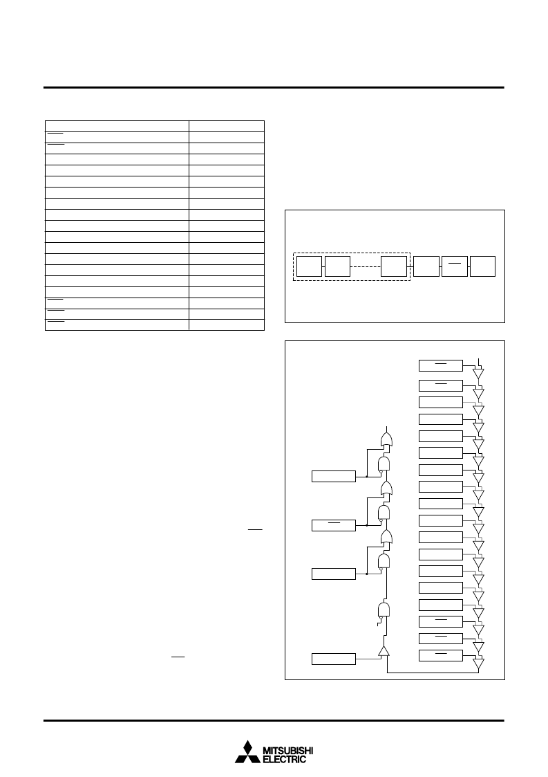
Figure 37 shows a diagram of the interrupt priority detection circuit
When an interrupt is caused, each interrupt device compares its own
priority with the priority from above and if its own priority is higher,
then it sends the priority below and requests the interrupt. If the pri-
orities are the same, the one above has priority.
This comparison is repeated to select the interrupt with the highest
priority among the interrupts that are being requested. Finally the
selected interrupt is compared with the processor interrupt priority
level (IPL) contained in the processor status register (PS) and the
request is accepted if it is higher than IPL and the interrupt disable
flag I is
“
0
”
. The request is not accepted if flag I is
“
1
”
. The reset, NMI,
and watchdog timer interrupts are not affected by the interrupt dis-
able flag I.
When an interrupt is accepted, the contents of the processor status
register (PS) is saved to the stack and the interrupt disable flag I is
set to
“
1
”
.
Furthermore, the interrupt request bit of the accepted interrupt is
cleared to
“
0
”
and the processor interrupt priority level (IPL) in the
processor status register (PS) is replaced by the priority level of the
accepted interrupt.
Therefore, multi-level priority interrupts are possible by resetting the
interrupt disable flag I to
“
0
”
and enable further interrupts.
For reset, watchdog timer, zero divide, NMI, and address match de-
tection interrupts, which do not have an interrupt control register, the
processor interrupt level (IPL) is set as shown in Table 10.
Table 9. Addresses of interrupt control registers
Interrupt control registers
INT
3
interrupt control register
INT
4
interrupt control register
A-D interrupt control register
UART0 transmit interrupt control register
UART0 receive interrupt control register
UART1 transmit interrupt control register
UART1 receive interrupt control register
Timer A0 interrupt control register
Timer A1 interrupt control register
Timer A2 interrupt control register
Timer A3 interrupt control register
Timer A4 interrupt control register
Timer B0 interrupt control register
Timer B1 interrupt control register
Timer B2 interrupt control register
INT
0
interrupt control register
INT
1
interrupt control register
INT
2
interrupt control register
Addresses
00006E
16
00006F
16
000070
16
000071
16
000072
16
000073
16
000074
16
000075
16
000076
16
000077
16
000078
16
000079
16
00007A
16
00007B
16
00007C
16
00007D
16
00007E
16
00007F
16
The interrupt request bit and the interrupt priority level of each inter-
rupt source are sampled and latched at each operation code fetch
cycle while f
sys
is
“
H
”
. However, no sampling pulse is generated until
the cycles whose number is selected by software has passed, even
if the next operation code fetch cycle is generated. The detection of
an interrupt which has the highest priority is performed during that
time.
Fig. 36 Interrupt priority
Fig. 37 Interrupt priority detection
Watchdog
timer
NMI
Priority is determined by hardware
A-D converter, UART, etc. interrupts
Priority can be changed by software inside
.
Reset
Reset
A-D
UART1 transmit
UART1 receive
UART0 transmit
UART0 receive
Timer B2
Timer B1
Timer B0
Timer A4
Timer A3
Timer A2
Timer A1
Timer A0
INT
2
NMI
Watchdog timer
IPL
Interrupt request
Level 0
Interrupt disable flag I
INT
3
INT
1
INT
0
INT
4
相關(guān)PDF資料 |
PDF描述 |
|---|---|
| M37902FCCHP | SINGLE-CHIP 16-BIT CMOS MICROCOMPUTER |
| M37902FGCHP | DIODE SCHOTTKY DUAL COMMON-ANODE 25V 150mW 0.32V-vf 200mA-IFM 1mA-IF 2uA-IR SOT-523 3K/REEL |
| M37902FJCHP | SINGLE-CHIP 16-BIT CMOS MICROCOMPUTER |
| M37905F8CFP | 16-BIT CMOS MICROCOMPUTER |
| M37905F8CSP | 16-BIT CMOS MICROCOMPUTER |
相關(guān)代理商/技術(shù)參數(shù) |
參數(shù)描述 |
|---|---|
| M37902FGCHP | 制造商:MITSUBISHI 制造商全稱:Mitsubishi Electric Semiconductor 功能描述:SINGLE-CHIP 16-BIT CMOS MICROCOMPUTER |
| M37902FJCHP | 制造商:MITSUBISHI 制造商全稱:Mitsubishi Electric Semiconductor 功能描述:SINGLE-CHIP 16-BIT CMOS MICROCOMPUTER |
| M37903S4CHP | 制造商:RENESAS 制造商全稱:Renesas Technology Corp 功能描述:16-BIT CMOS MICROCOMPUTER |
| M37905F8CFP | 制造商:MITSUBISHI 制造商全稱:Mitsubishi Electric Semiconductor 功能描述:16-BIT CMOS MICROCOMPUTER |
| M37905F8CSP | 制造商:MITSUBISHI 制造商全稱:Mitsubishi Electric Semiconductor 功能描述:16-BIT CMOS MICROCOMPUTER |
發(fā)布緊急采購(gòu),3分鐘左右您將得到回復(fù)。