- 您現(xiàn)在的位置:買賣IC網(wǎng) > PDF目錄383985 > USB97CFDC-MN (STANDARD MICROSYSTEMS CORP) USB FLOPPY DISK CONTROLLER PDF資料下載
參數(shù)資料
| 型號: | USB97CFDC-MN |
| 廠商: | STANDARD MICROSYSTEMS CORP |
| 元件分類: | 存儲控制器/管理單元 |
| 英文描述: | USB FLOPPY DISK CONTROLLER |
| 中文描述: | 1 Mbps, FLOPPY DISK DRIVE CONTROLLER, PQFP100 |
| 封裝: | 12 X 12 MM, TQFP-100 |
| 文件頁數(shù): | 35/59頁 |
| 文件大?。?/td> | 385K |
| 代理商: | USB97CFDC-MN |
第1頁第2頁第3頁第4頁第5頁第6頁第7頁第8頁第9頁第10頁第11頁第12頁第13頁第14頁第15頁第16頁第17頁第18頁第19頁第20頁第21頁第22頁第23頁第24頁第25頁第26頁第27頁第28頁第29頁第30頁第31頁第32頁第33頁第34頁當前第35頁第36頁第37頁第38頁第39頁第40頁第41頁第42頁第43頁第44頁第45頁第46頁第47頁第48頁第49頁第50頁第51頁第52頁第53頁第54頁第55頁第56頁第57頁第58頁第59頁

SMSC DS – USB97C201
Page 35
Rev. 03/25/2002
PRELIMINARY
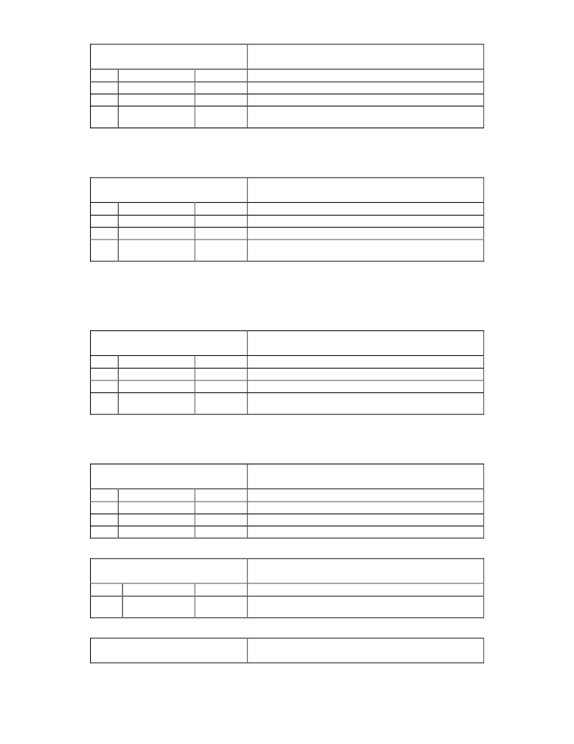
Table 37 –
Endpoint 0 Transmit Byte Count Register
EP0TX_BC
(0xB6 - RESET=0x00)
NAME
R/W
Reserved
R
This bit always reads “0”.
64BYTE
R/W
1 = Indicates that 64 Bytes are to be transmitted.
COUNT
R/W
Indicates the byte count of the packet to be sent on EP0
and stored in SRAM beginning at address 0x0040.
ENDPOINT 0 TRANSMIT BYTE COUNT REGISTER
DESCRIPTION
BIT
7
6
[5:0]
Note:
A zero length packet may be sent by just clearing this register and setting the TX bit in the EP0TX_CTL
register.
Table 38 –
Endpoint 1 Receive Byte Count Register
EP1RX_BC
(0xB7 - RESET=0x00)
NAME
R/W
Reserved
R
This bit always reads “0”.
64BYTE
R
1 = Indicates that 64 Bytes were received.
COUNT
R
Indicates the byte count of the packet received on EP1 and
stored in SRAM beginning at address 0x0080.
ENDPOINT 1 RECEIVE BYTE COUNT REGISTER
DESCRIPTION
BIT
7
6
[5:0]
Notes:
This register is updated at the end of a transfer and is actually the least significant bits of the ending address in
the SRAM buffer.
This register is cleared if a SETUP packet is received on EP0.
Table 39 –
Endpoint 1 Transmit Byte Count Register
EP1TX_BC
(0xC7 - RESET=0x00)
NAME
R/W
Reserved
R
This bit always reads “0”.
64BYTE
R/W
1 = Indicates that 64 Bytes are to be transmitted.
COUNT
R/W
Indicates the byte count of the packet to be sent on EP1
and stored in SRAM beginning at address 0x00C0.
ENDPOINT 1 TRANSMIT BYTE COUNT REGISTER
DESCRIPTION
BIT
7
6
[5:0]
Note:
A zero length packet may be sent by just clearing this register and setting the TX bit in the EP1TX_CTL
register.
Table 40 – RAM Buffer Write Byte Count Register A1
RAMWRBC_A1
(0xCE - RESET=0x00)
NAME
R/W
Reserved
R
This bit always reads “0”.
512Bytes
R
1 = Indicates that 512 bytes were transferred
COUNT8
R
Bit 8 of the byte count for the data transferred.
RAM BUFFER WRITE BYTE COUNT REGISTER A1
DESCRIPTION
BIT
[7:2]
1
0
Table 41 – RAM BUFFER WRITE Byte Count Register A2 Register
RAMWRBC_A2
(0xCF- RESET=0x00)
RAM BUFFER WRITE BYTE COUNT REGISTER A2
NAME
R/W
COUNT[7:0]
R
Bits 7 thru 0 the byte count of the data transferred to the
SRAM. The data is stored beginning at address 0x0100
BIT
[7:0]
DESCRIPTION
Table 42 – RAM Buffer Write Byte Count Register B1
RAMWRBC_B1
(0xD1 - RESET=0x00)
RAM BUFFER WRITE BYTE COUNT REGISTER B1
相關PDF資料 |
PDF描述 |
|---|---|
| USB97C202 | ATA/ATAPI CONTROLLER |
| USB97C202-MN-02 | ATA/ATAPI CONTROLLER |
| USB97C223 | capacitor Selection for Internal Regulator Output Pins |
| USB97C243 | capacitor Selection for Internal Regulator Output Pins |
| USB97CFDC | USB FLOPPY DISK CONTROLLER |
相關代理商/技術參數(shù) |
參數(shù)描述 |
|---|---|
| USB-A(M)-A(F)-1M-BEIGE | 制造商:SMART CABLE 功能描述: |
| USB-A-001A | 制造商:YAMAICHI 制造商全稱:Yamaichi Electronics Co., Ltd. 功能描述:Universal Serial Bus, Type A - 90° Receptacle |
| USB-A-001A-30 | 制造商:YAMAICHI 制造商全稱:Yamaichi Electronics Co., Ltd. 功能描述:Universal Serial Bus, Type A - 90° Receptacle |
| USB-A-002A | 制造商:YAMAICHI 制造商全稱:Yamaichi Electronics Co., Ltd. 功能描述:Universal Serial Bus, Type A - 90° Receptacle |
| USB-A-002A-30 | 制造商:YAMAICHI 制造商全稱:Yamaichi Electronics Co., Ltd. 功能描述:Universal Serial Bus, Type A - 90° Receptacle |
發(fā)布緊急采購,3分鐘左右您將得到回復。