- 您現(xiàn)在的位置:買賣IC網(wǎng) > PDF目錄383960 > TMP470R1B768PGE (Texas Instruments, Inc.) 16/32-Bit RISC Flash Microcontroller PDF資料下載
參數(shù)資料
| 型號: | TMP470R1B768PGE |
| 廠商: | Texas Instruments, Inc. |
| 英文描述: | 16/32-Bit RISC Flash Microcontroller |
| 中文描述: | 16/32位RISC閃存微控制器 |
| 文件頁數(shù): | 29/50頁 |
| 文件大小: | 393K |
| 代理商: | TMP470R1B768PGE |
第1頁第2頁第3頁第4頁第5頁第6頁第7頁第8頁第9頁第10頁第11頁第12頁第13頁第14頁第15頁第16頁第17頁第18頁第19頁第20頁第21頁第22頁第23頁第24頁第25頁第26頁第27頁第28頁當前第29頁第30頁第31頁第32頁第33頁第34頁第35頁第36頁第37頁第38頁第39頁第40頁第41頁第42頁第43頁第44頁第45頁第46頁第47頁第48頁第49頁第50頁
www.ti.com
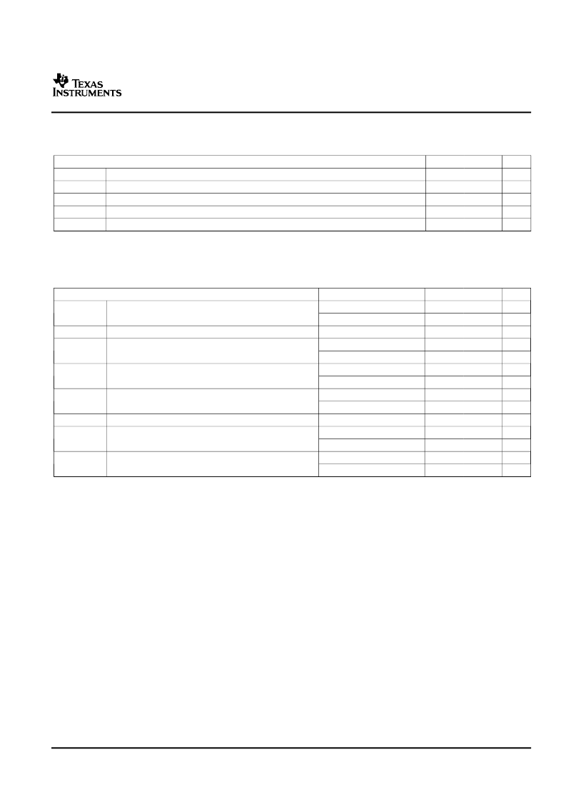
ZPLL AND CLOCK SPECIFICATIONS
Timing Requirements for ZPLL Circuits Enabled or Disabled
Switching Characteristics over Recommended Operating Conditions for Clocks
(1)(2)
TMS470R1B768
16/32-Bit RISC Flash Microcontroller
SPNS108A–AUGUST 2005–REVISED AUGUST 2006
MIN
MAX
UNIT
MHz
ns
ns
ns
kHz
f
(OSC)
t
c(OSC)
t
w(OSCIL)
t
w(OSCIH)
f
(OSCRST)
Input clock frequency
Cycle time, OSCIN
Pulse duration, OSCIN low
Pulse duration, OSCIN high
OSC FAIL frequency
(1)
4
20
50
15
15
53
(1)
Causes a device reset (specifically a clock reset) by setting the RST OSC FAIL (GLBCTRL.15) and the OSC FAIL flag (GLBSTAT.1)
bits equal to 1. For more detailed information on these bits and device resets, see the
TMS470R1x System Module Reference Guide
(literature number SPNU189).
PARAMETER
TEST CONDITIONS
(3)
Pipeline mode enabled
Pipeline mode disabled
Flash config mode
Pipeline mode enabled
Pipeline mode disabled
Pipeline mode enabled
Pipeline mode disabled
Pipeline mode enabled
Pipeline mode disabled
Flash config mode
Pipeline mode enabled
Pipeline mode disabled
Pipeline mode enabled
Pipeline mode disabled
MIN
MAX
UNIT
MHz
MHz
MHz
MHz
MHz
MHz
MHz
ns
ns
ns
ns
ns
ns
ns
60
24
24
25
24
25
24
f
(SYS)
System clock frequency
(4)
f
(CONFIG)
System clock frequency
f
(ICLK)
Interface clock frequency
f
(ECLK)
External clock output frequency for ECP module
16.7
41.6
41.6
40
41.6
40
41.6
t
c(SYS)
Cycle time, system clock
t
c(CONFIG)
Cycle time, system clock
t
c(ICLK)
Cycle time, interface clock
t
c(ECLK)
Cycle time, ECP module external clock output
(1)
When PLLDIS = 0, f
= M × f
/R, where M = {4 or 8}, R = {1,2,3,4,5,6,7,8}. R is the system-clock divider determined by the
CLKDIVPRE [2:0] bits in the global control register (GLBCTRL[2:0]) and M is the PLL multiplier determined by the MULT4 bit
(GLBCTRL.3).
When PLLDIS = 1, f
= f
/R, where R = {1,2,3,4,5,6,7,8}.
f
= f
/X, where X = {1,2,3,4,5,6,7,8,9,10,11,12,13,14,15,16}. X is the interface clock divider ratio determined by the PCR0[4:1]
bits in the SYS module.
f
= f
/N, where N = {1 to 256}. N is the ECP prescale value defined by the ECPCTRL[7:0] register bits in the ECP module.
Pipeline mode enabled or disabled is determined by the ENPIPE bit (FMREGOPT.0).
Flash Vread must be set to 5 V to achieve maximum system clock frequency.
(2)
(3)
(4)
29
Submit Documentation Feedback
相關(guān)PDF資料 |
PDF描述 |
|---|---|
| TMP47C020 | Transient Voltage Suppressor Diodes |
| TMP47C020G | Transient Voltage Suppressor Diodes |
| TMP47C050 | Transient Voltage Suppressor Diodes |
| TMP47C050E | Transient Voltage Suppressor Diodes |
| TMP47C050G | Transient Voltage Suppressor Diodes |
相關(guān)代理商/技術(shù)參數(shù) |
參數(shù)描述 |
|---|---|
| TMP470R1F369APGEQ | 制造商:Texas Instruments 功能描述: |
| TMP470R1VF338PZQ | 制造商:Texas Instruments 功能描述:- Rail/Tube |
| TMP470R1VF478GJZQ | 制造商:Texas Instruments 功能描述: |
| TMP4720/7440P/N | 制造商:未知廠家 制造商全稱:未知廠家 功能描述: |
| TMP4720F | 制造商:未知廠家 制造商全稱:未知廠家 功能描述:4-Bit Microcontroller |
發(fā)布緊急采購,3分鐘左右您將得到回復。