- 您現(xiàn)在的位置:買(mǎi)賣(mài)IC網(wǎng) > PDF目錄367854 > PDI1394L41 (NXP Semiconductors N.V.) Content Protection AV Link Layer(內(nèi)容可保護(hù)的AV鏈接層控制器) PDF資料下載
參數(shù)資料
| 型號(hào): | PDI1394L41 |
| 廠商: | NXP Semiconductors N.V. |
| 英文描述: | Content Protection AV Link Layer(內(nèi)容可保護(hù)的AV鏈接層控制器) |
| 中文描述: | 影音內(nèi)容保護(hù)鏈路層(內(nèi)容可保護(hù)的視聽(tīng)鏈接層控制器) |
| 文件頁(yè)數(shù): | 53/81頁(yè) |
| 文件大小: | 303K |
| 代理商: | PDI1394L41 |
第1頁(yè)第2頁(yè)第3頁(yè)第4頁(yè)第5頁(yè)第6頁(yè)第7頁(yè)第8頁(yè)第9頁(yè)第10頁(yè)第11頁(yè)第12頁(yè)第13頁(yè)第14頁(yè)第15頁(yè)第16頁(yè)第17頁(yè)第18頁(yè)第19頁(yè)第20頁(yè)第21頁(yè)第22頁(yè)第23頁(yè)第24頁(yè)第25頁(yè)第26頁(yè)第27頁(yè)第28頁(yè)第29頁(yè)第30頁(yè)第31頁(yè)第32頁(yè)第33頁(yè)第34頁(yè)第35頁(yè)第36頁(yè)第37頁(yè)第38頁(yè)第39頁(yè)第40頁(yè)第41頁(yè)第42頁(yè)第43頁(yè)第44頁(yè)第45頁(yè)第46頁(yè)第47頁(yè)第48頁(yè)第49頁(yè)第50頁(yè)第51頁(yè)第52頁(yè)當(dāng)前第53頁(yè)第54頁(yè)第55頁(yè)第56頁(yè)第57頁(yè)第58頁(yè)第59頁(yè)第60頁(yè)第61頁(yè)第62頁(yè)第63頁(yè)第64頁(yè)第65頁(yè)第66頁(yè)第67頁(yè)第68頁(yè)第69頁(yè)第70頁(yè)第71頁(yè)第72頁(yè)第73頁(yè)第74頁(yè)第75頁(yè)第76頁(yè)第77頁(yè)第78頁(yè)第79頁(yè)第80頁(yè)第81頁(yè)
Philips Semiconductors
Preliminary specification
PDI1394L41
1394 content protection AV link layer controller
2000 Apr 15
50
13.1.6
This register provides access to the internal registers on the Phy. There are special considerations when reading or writing to this register. When
reading a PHY register, the address of the register is written to the PHYRGAD field with the RDPHY bit set. The PHY data will be valid when the
PHYRRX bit (LNKPHYINTACK register bit 14) is set. Once this happens the register data is available in the PHYRXDATA, the address of the
register just read is also available in the PHYRXAD fields. When writing a Phy register, the address of the register to be written is set in the
PHYRGAD field and the data to be written to the register is set in PHYRGDATA, along with the WRPHY bit being set. Once the write is
complete, the WRPHY bit will be cleared. Do not write a new Read/Write command until the previous one has been completed. After the Self-ID
phase, PHY register 0 will be read automatically.
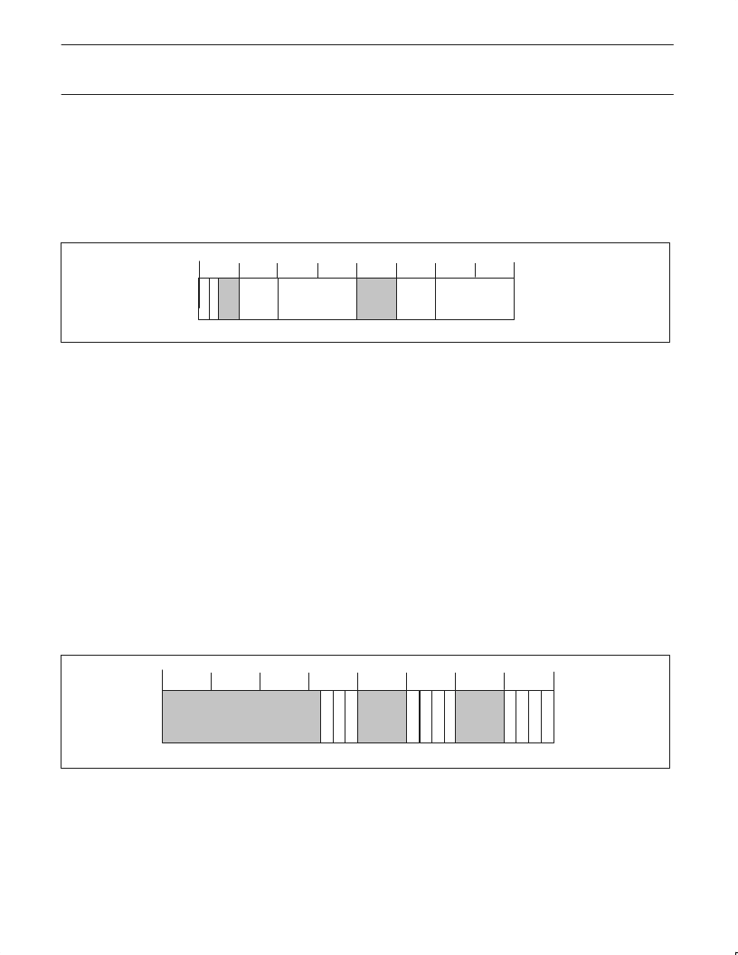
Phy Register Access (PHYACS) – Base Address: 0x014
29 28 272625 24 23 22 212019 18 1716 15 1413 12 11 10 9 8 7 6 5 4 3 2 1 0
R
W
SV00277
PHYRGAD
PHYRGDATA
PHYRXAD
PHYRXDATA
31 30
Reset Value 0x00000000
Bit 31:
R/W
Read Phy Chip Register (RDPHY): When asserted, the PDI1394L41 sends a read register request with address
equal to Phy Rg Ad to the Phy interface. This bit is cleared when the request is sent.
Write Phy Chip Register (WRPHY): When asserted, the PDI1394L41 sends a write register request with address
equal to Phy Rg Ad to the Phy interface. This bit is cleared when the request is sent.
Phy Chip Register Address (PHYRGAD): This is the address of the Phy-chip register that is to be accessed.
Phy Chip Register Data (PHYRGDATA): This is the data to be written to the Phy-chip register indicated in Phy Rg Ad.
Phy Chip Register Received Address (PHYRXAD): Address of register from which Phy Rx Data came.
Phy Chip Register Received Data (PHYRXDATA): Data from register addressed by Phy Rx Ad.
Bit 30:
R/W
Bit 27..24:
Bit 23..16:
Bit 11..8:
Bit 7..0:
R/W
R/W
R
R
13.1.7
This register is the top level interrupt status register. If the external interrupt line is set, this register will indicate which major portion of the AV
Link generated the interrupt. There is no interrupt acknowledge required at this level. These bits auto clear when the interrupts in the
appropriate section of the device are cleared or disabled. Control of the AV transceiver is also provided by this register.
Global Interrupt Status and TX Control (GLOBCSR) – Base Address: 0x018
Bits 0 to 3 are used to identify which internal modules are currently generating an interrupt. After identifying the module, the appropriate register
in that module must be read to determine the exact cause of the interrupt.
A timer is available to aid the implementation of higher level protocols such as AV/C and HAVi. The timer can be started and stopped, and
automatically reloads with 1s (TIMLOAD = 1) or 100ms (TIMLOAD = 0). When the set time has expired, an interrupt will be generated through
TIMER (Bit 20, LNKPHYINTACK 0x008). In normal timer mode (TIMMODE = 0), the timer will generate an interrupt, reload and restart every
time it expires, until TIMRNSTP is cleared. In bus reset timer mode (TIMMODE = 1), even when already running the timer will reload with 1s
and restart automatically after a bus reset. If another bus reset occurs before the timer expires, the timer will again reload and restart. No
interrupt will be generated until the timer expires.
29 28 27 26 25 24 23 22 21 20 19 18 17 16 15 14 13 12 11 10
9
8
7
6
5
4
3
2
1
0
A
I
I
L
31 30
E
E
E
E
D
E
E
SV01024
NOTES
1. There can be more than one interrupt source active at the same time.
2. The HIF INT_N signal (pin 28) remains active as long as there is at least one more enabled active interrupt status bit.
Reset Value 0x00010000
Bit 18:
R/W
Enable output AVPORT2: A ‘1’ enables AVPORT2 as an output. A ‘0’ sets the 3-State condition on the port. In
3-State condition the port may be used as an input or unused output according to the state of DIRAV1 (bit 16).
Enable output AVPORT1: A ‘1’ enables AVPORT1 as an output. A ‘0’ sets the 3-State condition on the port. In
3-State condition the port may be used as an input or unused output according to the state of DIRAV1 (bit 16).
Bit 17:
R/W
相關(guān)PDF資料 |
PDF描述 |
|---|---|
| PDI1394P21 | 3-port Physical Layer Interface(三端口物理層接口) |
| PDI1394P22 | 3-port Physical Layer Interface(三端口物理層接口) |
| PDI1394P24 | 2-port 400 Mbps physical layer interface(2端口 400 Mbps物理層接口) |
| PDI40C1D00 | |
| PDI40C1300 | |
相關(guān)代理商/技術(shù)參數(shù) |
參數(shù)描述 |
|---|---|
| PDI1394L41BE | 制造商:PHILIPS 制造商全稱(chēng):NXP Semiconductors 功能描述:1394 content protection AV link layer controller |
| PDI1394P11 | 制造商:PHILIPS 制造商全稱(chēng):NXP Semiconductors 功能描述:3-port physical layer interface |
| PDI1394P11A | 制造商:PHILIPS 制造商全稱(chēng):NXP Semiconductors 功能描述:3-port physical layer interface |
| PDI1394P11ABD | 制造商:PHILIPS 制造商全稱(chēng):NXP Semiconductors 功能描述:3-port physical layer interface |
| PDI1394P11ABD-S | 制造商:未知廠家 制造商全稱(chēng):未知廠家 功能描述:Transceiver |
發(fā)布緊急采購(gòu),3分鐘左右您將得到回復(fù)。