- 您現(xiàn)在的位置:買賣IC網(wǎng) > PDF目錄357780 > EM6617VVVST11A 4-BIT, MROM, 0.032768 MHz, RISC MICROCONTROLLER PDF資料下載
參數(shù)資料
| 型號(hào): | EM6617VVVST11A |
| 元件分類: | 微控制器/微處理器 |
| 英文描述: | 4-BIT, MROM, 0.032768 MHz, RISC MICROCONTROLLER |
| 封裝: | STICKY TAPE |
| 文件頁數(shù): | 9/66頁 |
| 文件大小: | 759K |
| 代理商: | EM6617VVVST11A |
第1頁第2頁第3頁第4頁第5頁第6頁第7頁第8頁當(dāng)前第9頁第10頁第11頁第12頁第13頁第14頁第15頁第16頁第17頁第18頁第19頁第20頁第21頁第22頁第23頁第24頁第25頁第26頁第27頁第28頁第29頁第30頁第31頁第32頁第33頁第34頁第35頁第36頁第37頁第38頁第39頁第40頁第41頁第42頁第43頁第44頁第45頁第46頁第47頁第48頁第49頁第50頁第51頁第52頁第53頁第54頁第55頁第56頁第57頁第58頁第59頁第60頁第61頁第62頁第63頁第64頁第65頁第66頁
EM6617-1
EM Microlectronic-Marin SA , 3/99 Rev. B/258
9
5.1 Oscillation Detection Circuit
At power on, the voltage regulator starts to follow the supply voltage and triggers the power on reset circuitry,
and thus the system reset. The CPU of the EM6617-1 remains in the reset state for the ‘CPU Reset Delay’, to
allow the oscillator to stabilize after power up.
The oscillator is disabled during sleep mode. So when waking up from sleep mode, the CPU of the EM6617-1
remains in the reset state for the CPU Reset Delay, to allow the oscillator to stabilize. During this time, the
Oscillation Detection Circuit is inhibited.
In active or standby modes, the oscillator detection circuit monitors the oscillator. If it stops for any reason, a
system reset is generated. After clock restart the CPU waits for the CPU Reset Delay before executing the first
instructions.
The oscillation detection circuitry can be inhibited with bit
NoOscWD
= 1 in register
RegSysCntl3.
At power up,
and after any system reset, the function is activated.
The ‘CPU Reset Delay’ is 32768 system clocks ( Ck[16] ) long.
5.2 Reset Terminal
During active or standby modes the Reset terminal has a debouncer to reject noise. Reset must therefore be
active for at least 16 ms (system clock = 32 KHz).
When canceling sleep mode, the debouncer is not active (no clock), however, reset passes through an
analogue filter with a time constant of typical. 5μs. In this case Reset pin must be high for at least 10 μs to
generate a system reset.
5.3 Input Port A Reset Function
By writing the
OptInpRSel1
and
OptInpRSel2
registers it is possible to choose any combination of port A input
values to execute a system reset. The reset condition must be valid for at least 16ms (system clock = 32kHz) in
active and standby mode.
OPTInpRSleep
selects the input port A reset function in sleep mode. If set to "1" the occurrence of the selected
combination for input port A reset will immediately trigger a system reset (no debouncer) .
Reset combination selection (
InpReset)
is done with registers
OptInpRSel1
and
OptInpRSel2.
Either an ‘AND’ or an ‘OR’ type port A combination can be chosen to generate the reset.
5.3.1 AND-Type Reset function
Default setting(metal option). One or a combination of port A inputs will trigger a reset. Following formula is
applicable :
InpResPA
=
InpResPA[0]
InpResPA[1]
InpResPA[2]
InpResPA[3]
InpRes1PA[n]
0
0
1
1
n = 0 to 3
InpRes2PA[n]
0
1
0
1
InpResPA[n]
V
SS
PA[n]
not PA[n]
V
DD
i.e. ; - no reset if InpResPA[n] = V
SS
.
- Don't care function on a single bit with
its InpResPA[n] = V
DD
.
- Always Reset if InpResPA[3:0] = 'b1111
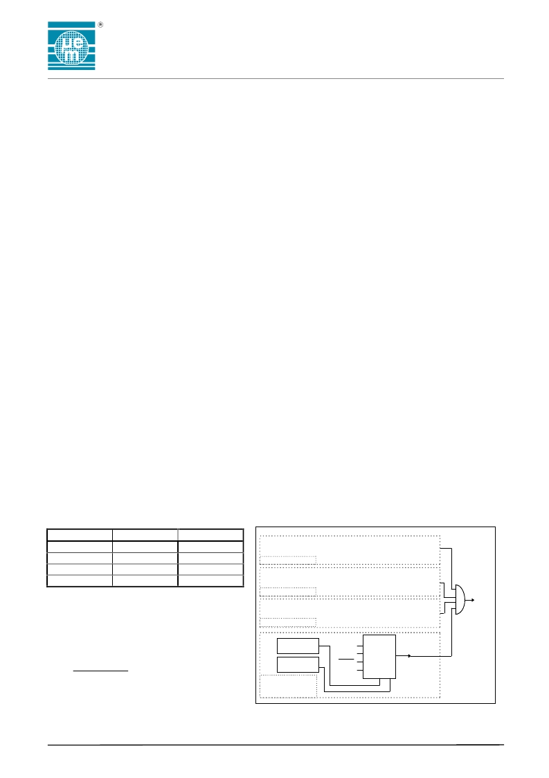
Figure 9. Input Port A Reset Structure
0
1 MUX
2
3 1 0
V
SS
PA[3]
PA[3]
V
DD
BIT
[0]
BIT
[1]
BIT
[2]
BIT
[3]
InpResPA
InpResPA[3]
InpRes2PA[3]
InpRes1PA[3]
Input Port A Reset
Bit[2] Selection
Input Port A Reset
Bit[1] Selection
Input Port A Reset
Bit[0] Selection
Input Port A Reset
Bit[3] Selection
Input
Reset
from
Port A
相關(guān)PDF資料 |
PDF描述 |
|---|---|
| EMCL12M2H-187.5103MTR | CRYSTAL OSCILLATOR, CLOCK, 187.5103 MHz, LVPECL OUTPUT |
| EMDS22N2J-156.250M | CRYSTAL OSCILLATOR, CLOCK, 156.25 MHz, LVDS OUTPUT |
| EMDS23C2H-10.000M | CRYSTAL OSCILLATOR, CLOCK, 10 MHz, LVDS OUTPUT |
| EMDS23E2H-77.760MTR | CRYSTAL OSCILLATOR, CLOCK, 77.76 MHz, LVDS OUTPUT |
| EMIF4-100FCD4 | EMI FILTER/TVS ARRAY |
相關(guān)代理商/技術(shù)參數(shù) |
參數(shù)描述 |
|---|---|
| EM6617WP11 | 制造商:EMMICRO 制造商全稱:EM Microelectronic - MARIN SA 功能描述:Ultra Low Power Microcontroller with ADC AND EEPROM |
| EM6617WP27 | 制造商:EMMICRO 制造商全稱:EM Microelectronic - MARIN SA 功能描述:Ultra Low Power Microcontroller with ADC AND EEPROM |
| EM6617WS11 | 制造商:EMMICRO 制造商全稱:EM Microelectronic - MARIN SA 功能描述:Ultra Low Power Microcontroller with ADC AND EEPROM |
| EM6617WS27 | 制造商:EMMICRO 制造商全稱:EM Microelectronic - MARIN SA 功能描述:Ultra Low Power Microcontroller with ADC AND EEPROM |
| EM6617WW11 | 制造商:EMMICRO 制造商全稱:EM Microelectronic - MARIN SA 功能描述:Ultra Low Power Microcontroller with ADC AND EEPROM |
發(fā)布緊急采購,3分鐘左右您將得到回復(fù)。