- 您現(xiàn)在的位置:買賣IC網(wǎng) > PDF目錄297644 > UPSD3253B-40T6 (STMICROELECTRONICS) 8-BIT, FLASH, 40 MHz, MICROCONTROLLER, PQFP52 PDF資料下載
參數(shù)資料
| 型號(hào): | UPSD3253B-40T6 |
| 廠商: | STMICROELECTRONICS |
| 元件分類: | 微控制器/微處理器 |
| 英文描述: | 8-BIT, FLASH, 40 MHz, MICROCONTROLLER, PQFP52 |
| 封裝: | PLASTIC, TQFP-52 |
| 文件頁數(shù): | 149/189頁 |
| 文件大小: | 1638K |
| 代理商: | UPSD3253B-40T6 |
第1頁第2頁第3頁第4頁第5頁第6頁第7頁第8頁第9頁第10頁第11頁第12頁第13頁第14頁第15頁第16頁第17頁第18頁第19頁第20頁第21頁第22頁第23頁第24頁第25頁第26頁第27頁第28頁第29頁第30頁第31頁第32頁第33頁第34頁第35頁第36頁第37頁第38頁第39頁第40頁第41頁第42頁第43頁第44頁第45頁第46頁第47頁第48頁第49頁第50頁第51頁第52頁第53頁第54頁第55頁第56頁第57頁第58頁第59頁第60頁第61頁第62頁第63頁第64頁第65頁第66頁第67頁第68頁第69頁第70頁第71頁第72頁第73頁第74頁第75頁第76頁第77頁第78頁第79頁第80頁第81頁第82頁第83頁第84頁第85頁第86頁第87頁第88頁第89頁第90頁第91頁第92頁第93頁第94頁第95頁第96頁第97頁第98頁第99頁第100頁第101頁第102頁第103頁第104頁第105頁第106頁第107頁第108頁第109頁第110頁第111頁第112頁第113頁第114頁第115頁第116頁第117頁第118頁第119頁第120頁第121頁第122頁第123頁第124頁第125頁第126頁第127頁第128頁第129頁第130頁第131頁第132頁第133頁第134頁第135頁第136頁第137頁第138頁第139頁第140頁第141頁第142頁第143頁第144頁第145頁第146頁第147頁第148頁當(dāng)前第149頁第150頁第151頁第152頁第153頁第154頁第155頁第156頁第157頁第158頁第159頁第160頁第161頁第162頁第163頁第164頁第165頁第166頁第167頁第168頁第169頁第170頁第171頁第172頁第173頁第174頁第175頁第176頁第177頁第178頁第179頁第180頁第181頁第182頁第183頁第184頁第185頁第186頁第187頁第188頁第189頁
Obsolete
Product(s)
- Obsolete
Product(s)
Timer/counters (Timer 0, Timer 1 and Timer 2)
UPSD3254A, UPSD3254BV, UPSD3253B,
11.1.4
Mode 3
Timer 1 in Mode 3 simply holds its count. The effect is the same as setting TR1 = 0.
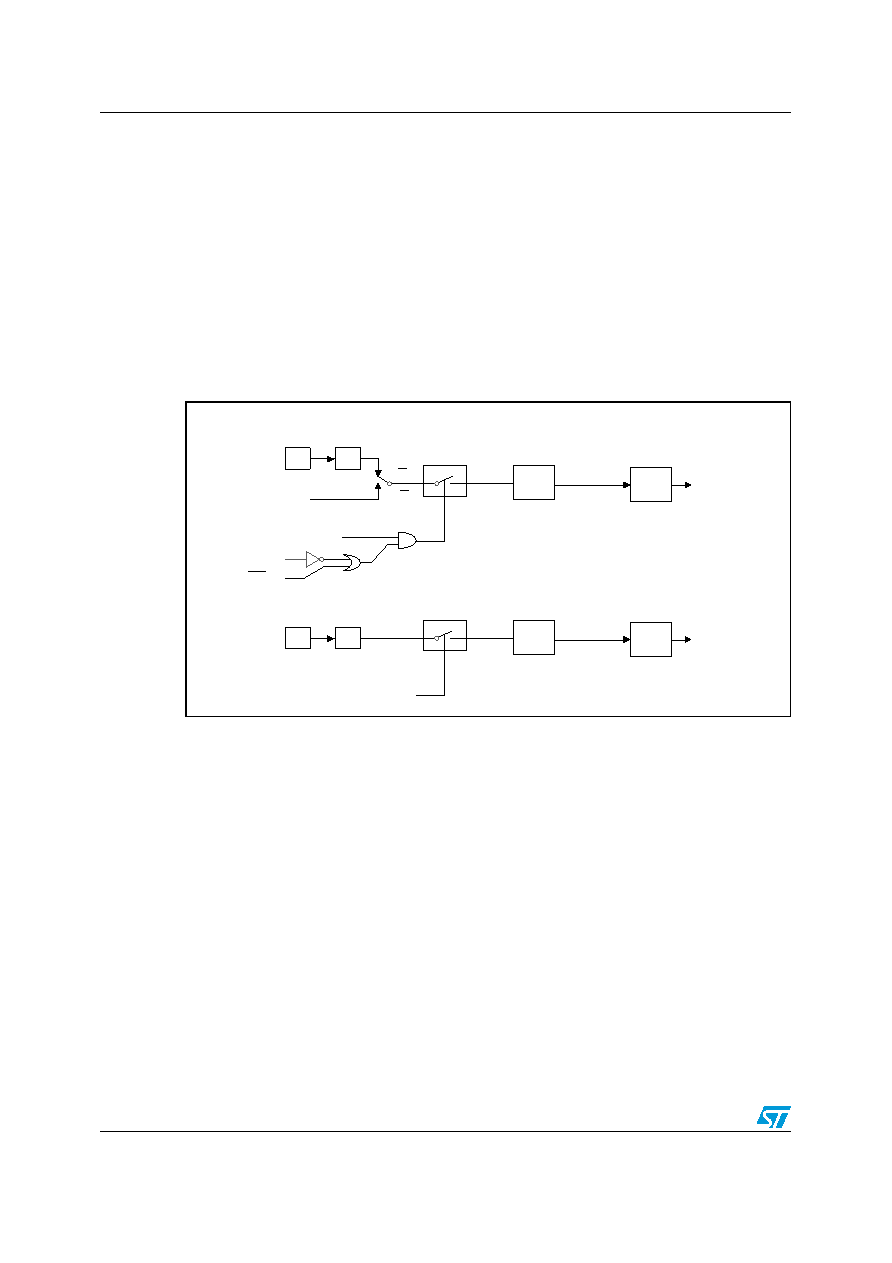
Timer 0 in Mode 3 establishes TL0 and TH0 as two separate counters. The logic for Mode 3
on Timer 0 is shown in Figure 23. TL0 uses the Timer 0 control Bits: C/T, GATE, TR0, INT0,
and TF0. TH0 is locked into a timer function (counting machine cycles) and takes over the
use of TR1 and TF1 from Timer 1. Thus, TH0 now controls the “Timer 1“ Interrupt.
Mode 3 is provided for applications requiring an extra 8-bit timer on the counter. With Timer
0 in Mode 3, an UPSD325xx devices can look like it has three Timer/Counters. When Timer
0 is in Mode 3, Timer 1 can be turned on and off by switching it out of and into its own Mode
3, or can still be used by the serial port as a baud rate generator, or in fact, in any application
not requiring an interrupt.
Figure 23.
Timer/counter mode 3: two 8-bit counters
11.2
Timer 2
Like Timers 0 and 1, Timer 2 can operate as either an event timer or as an event counter.
This is selected by Bit C/T2 in the special function register T2CON. It has three operating
modes: Capture, Auto-reload, and Baud Rate Generator, which are selected by bits in the
T2CON as shown in Table 41. In the Capture mode there are two options which are selected
by Bit EXEN2 in T2CON. if EXEN2 = 0, then Timer 2 is a 16-bit timer or counter which upon
overflowing sets Bit TF2, the Timer 2 Overflow bit, which can be used to generate an
interrupt. If EXEN2 = 1, then Timer 2 still does the above, but with the added feature that a
1-to-0 transition at external input T2EX causes the current value in the Timer 2 registers,
TL2 and TH2, to be captured into registers RCAP2L and RCAP2H, respectively. In addition,
the transition at T2EX causes Bit EXF2 in T2CON to be set, and EXF2 like TF2 can
generate an interrupt. The Capture mode is illustrated in Figure 24.
In the Auto-reload mode, there are again two options, which are selected by bit EXEN2 in
T2CON. If EXEN2 = 0, then when Timer 2 rolls over it not only sets TF2 but also causes the
Timer 2 registers to be reloaded with the 16-bit value in registers RCAP2L and RCAP2H,
which are preset by software. If EXEN2 = 1, then Timer 2 still does the above, but with the
added feature that a 1-to-0 transition at external input T2EX will also trigger the 16-bit reload
AI06624
fOSC
TF0
Interrupt
Gate
TR0
INT0 pin
T0 pin
Control
TL0
(8 bits)
C/T = 0
C/T = 1
÷ 12
fOSC
TF1
Interrupt
Control
TH1
(8 bits)
÷ 12
TR1
相關(guān)PDF資料 |
PDF描述 |
|---|---|
| UPSD3334D-40U6 | 8-BIT, FLASH, 40 MHz, MICROCONTROLLER, PQFP80 |
| US1001FL | 0.5 A, 100 V, SILICON, SIGNAL DIODE |
| US1A-HE3 | 1 A, 50 V, SILICON, SIGNAL DIODE, DO-214AC |
| US1B-HE3 | 1 A, 100 V, SILICON, SIGNAL DIODE, DO-214AC |
| US1G-HE3 | 1 A, 400 V, SILICON, SIGNAL DIODE, DO-214AC |
相關(guān)代理商/技術(shù)參數(shù) |
參數(shù)描述 |
|---|---|
| UPSD3253B-40T6T | 制造商:STMICROELECTRONICS 制造商全稱:STMicroelectronics 功能描述:Flash Programmable System Device with 8032 Microcontroller Core |
| UPSD3253B-40U1 | 制造商:STMICROELECTRONICS 制造商全稱:STMicroelectronics 功能描述:Flash Programmable System Device with 8032 Microcontroller Core |
| UPSD3253B-40U1T | 制造商:STMICROELECTRONICS 制造商全稱:STMicroelectronics 功能描述:Flash Programmable System Device with 8032 Microcontroller Core |
| UPSD3253B-40U6 | 制造商:STMICROELECTRONICS 制造商全稱:STMicroelectronics 功能描述:Flash Programmable System Device with 8032 Microcontroller Core |
| UPSD3253B-40U6T | 制造商:STMICROELECTRONICS 制造商全稱:STMicroelectronics 功能描述:Flash Programmable System Device with 8032 Microcontroller Core |
發(fā)布緊急采購,3分鐘左右您將得到回復(fù)。