- 您現(xiàn)在的位置:買賣IC網(wǎng) > PDF目錄383982 > UPD6708CX (NEC Corp.) IEBusa Inter Equipment Busa PROTOCOL CONTROL LSI PDF資料下載
參數(shù)資料
| 型號: | UPD6708CX |
| 廠商: | NEC Corp. |
| 英文描述: | IEBusa Inter Equipment Busa PROTOCOL CONTROL LSI |
| 中文描述: | IEBusa設備布薩間協(xié)議控制大規(guī)模集成電路 |
| 文件頁數(shù): | 42/72頁 |
| 文件大小: | 292K |
| 代理商: | UPD6708CX |
第1頁第2頁第3頁第4頁第5頁第6頁第7頁第8頁第9頁第10頁第11頁第12頁第13頁第14頁第15頁第16頁第17頁第18頁第19頁第20頁第21頁第22頁第23頁第24頁第25頁第26頁第27頁第28頁第29頁第30頁第31頁第32頁第33頁第34頁第35頁第36頁第37頁第38頁第39頁第40頁第41頁當前第42頁第43頁第44頁第45頁第46頁第47頁第48頁第49頁第50頁第51頁第52頁第53頁第54頁第55頁第56頁第57頁第58頁第59頁第60頁第61頁第62頁第63頁第64頁第65頁第66頁第67頁第68頁第69頁第70頁第71頁第72頁
42
μ
PD6708
Table 6-7. Minimum Generation Intervals for Return Codes in Master Reception (
μ
s)
Time
Mode 0
Mode 1
Mode 2
T1
Note
Approx. 8030
Approx. 5800
T2
Approx. 1580
Approx. 400
Approx. 290
T3
Approx. 10
Approx. 10
Approx. 10
T4
Approx. 7290
Approx. 2050
Approx. 1550
Note
The mode 0 master receive data consists of up to 19 bytes. There-
fore, the receive buffer (20 bytes) does not become full, and a return
code is not generated.
(4)
Slave reception
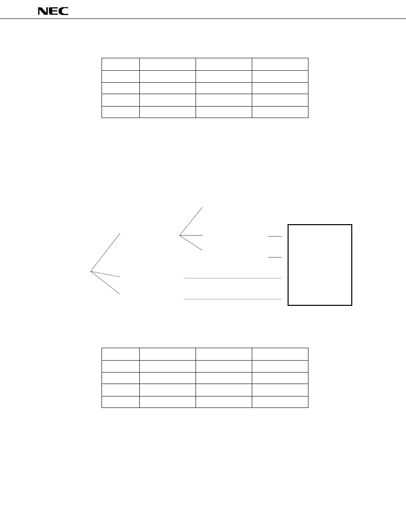
The order of generation of slave reception return codes is as shown in Figure 6-4.
Figure 6-4. Return Code Generation Order in Slave Reception
The minimum generation intervals for return codes in master transmission are shown below.
Table 6-8. Minimum Generation Intervals for Return Codes in Slave Reception (
μ
s)
Note
The mode 0 master receive data consists of up to 19 bytes. There-
fore, the receive buffer (20 bytes) does not become full, and a return
code is not generated.
(5)
Broadcast reception
The return code generation order and minimum generation intervals in the case of broadcast reception are the same
as for
(4) Slave reception
as shown above.
Time
Mode 0
Mode 1
Mode 2
T1
Note
Approx. 8030
Approx. 5800
T2
Approx. 1580
Approx. 400
Approx. 290
T3
Approx. 10
Approx. 10
Approx. 10
T4
Approx. 7290
Approx. 2050
Approx. 1550
Slave Reception
Start
(Return Code
: 1000)
Slave Receive
Buffer Full
(Return Code : 1001)
T3
New communication
return codes
Slave reception start
(Return code : 1000)
Broadcast reception
start
(Return code : 1100)
etc.
T1
T2
T3
Slave Reception
Normal Termination
(Return Code : 1010)
Termination During
Slave Reception
(Return Code : 1011)
T2
T1
Slave Receive
Buffer Full
(Return Code : 1001)
Slave Reception
Normal Termination
(Return Code : 1010)
Termination During
Slave Reception
(Return Code : 1011)
T4
T4
T4
T4
相關PDF資料 |
PDF描述 |
|---|---|
| UPD6708GS | IEBusa Inter Equipment Busa PROTOCOL CONTROL LSI |
| UPD6951 | 6 BIT D/A CONVERTER FOR VIDEO SIGNAL PROCESSING CMOS LSI |
| UPD6951C | 6 BIT D/A CONVERTER FOR VIDEO SIGNAL PROCESSING CMOS LSI |
| UPD6951G | 6 BIT D/A CONVERTER FOR VIDEO SIGNAL PROCESSING CMOS LSI |
| UPD703130GC-8EU | MOS INTEGRATED CIRCUIT |
相關代理商/技術參數(shù) |
參數(shù)描述 |
|---|---|
| UPD6708GS | 制造商:NEC 制造商全稱:NEC 功能描述:IEBusa Inter Equipment Busa PROTOCOL CONTROL LSI |
| UPD6708GS(A) | 制造商:Renesas Electronics Corporation 功能描述: |
| UPD67100 | 制造商:未知廠家 制造商全稱:未知廠家 功能描述:ASIC |
| UPD67101 | 制造商:未知廠家 制造商全稱:未知廠家 功能描述:ASIC |
| UPD67240 | 制造商:未知廠家 制造商全稱:未知廠家 功能描述:ASIC |
發(fā)布緊急采購,3分鐘左右您將得到回復。