- 您現(xiàn)在的位置:買賣IC網(wǎng) > PDF目錄98306 > TVP5160PNP (TEXAS INSTRUMENTS INC) COLOR SIGNAL DECODER, PQFP128 PDF資料下載
參數(shù)資料
| 型號(hào): | TVP5160PNP |
| 廠商: | TEXAS INSTRUMENTS INC |
| 元件分類: | 顏色信號(hào)轉(zhuǎn)換 |
| 英文描述: | COLOR SIGNAL DECODER, PQFP128 |
| 封裝: | GREEN, PLASTIC, HTQFP-128 |
| 文件頁(yè)數(shù): | 61/111頁(yè) |
| 文件大?。?/td> | 1400K |
| 代理商: | TVP5160PNP |
第1頁(yè)第2頁(yè)第3頁(yè)第4頁(yè)第5頁(yè)第6頁(yè)第7頁(yè)第8頁(yè)第9頁(yè)第10頁(yè)第11頁(yè)第12頁(yè)第13頁(yè)第14頁(yè)第15頁(yè)第16頁(yè)第17頁(yè)第18頁(yè)第19頁(yè)第20頁(yè)第21頁(yè)第22頁(yè)第23頁(yè)第24頁(yè)第25頁(yè)第26頁(yè)第27頁(yè)第28頁(yè)第29頁(yè)第30頁(yè)第31頁(yè)第32頁(yè)第33頁(yè)第34頁(yè)第35頁(yè)第36頁(yè)第37頁(yè)第38頁(yè)第39頁(yè)第40頁(yè)第41頁(yè)第42頁(yè)第43頁(yè)第44頁(yè)第45頁(yè)第46頁(yè)第47頁(yè)第48頁(yè)第49頁(yè)第50頁(yè)第51頁(yè)第52頁(yè)第53頁(yè)第54頁(yè)第55頁(yè)第56頁(yè)第57頁(yè)第58頁(yè)第59頁(yè)第60頁(yè)當(dāng)前第61頁(yè)第62頁(yè)第63頁(yè)第64頁(yè)第65頁(yè)第66頁(yè)第67頁(yè)第68頁(yè)第69頁(yè)第70頁(yè)第71頁(yè)第72頁(yè)第73頁(yè)第74頁(yè)第75頁(yè)第76頁(yè)第77頁(yè)第78頁(yè)第79頁(yè)第80頁(yè)第81頁(yè)第82頁(yè)第83頁(yè)第84頁(yè)第85頁(yè)第86頁(yè)第87頁(yè)第88頁(yè)第89頁(yè)第90頁(yè)第91頁(yè)第92頁(yè)第93頁(yè)第94頁(yè)第95頁(yè)第96頁(yè)第97頁(yè)第98頁(yè)第99頁(yè)第100頁(yè)第101頁(yè)第102頁(yè)第103頁(yè)第104頁(yè)第105頁(yè)第106頁(yè)第107頁(yè)第108頁(yè)第109頁(yè)第110頁(yè)第111頁(yè)
SLES135E
– FEBRUARY 2005 – REVISED APRIL 2011
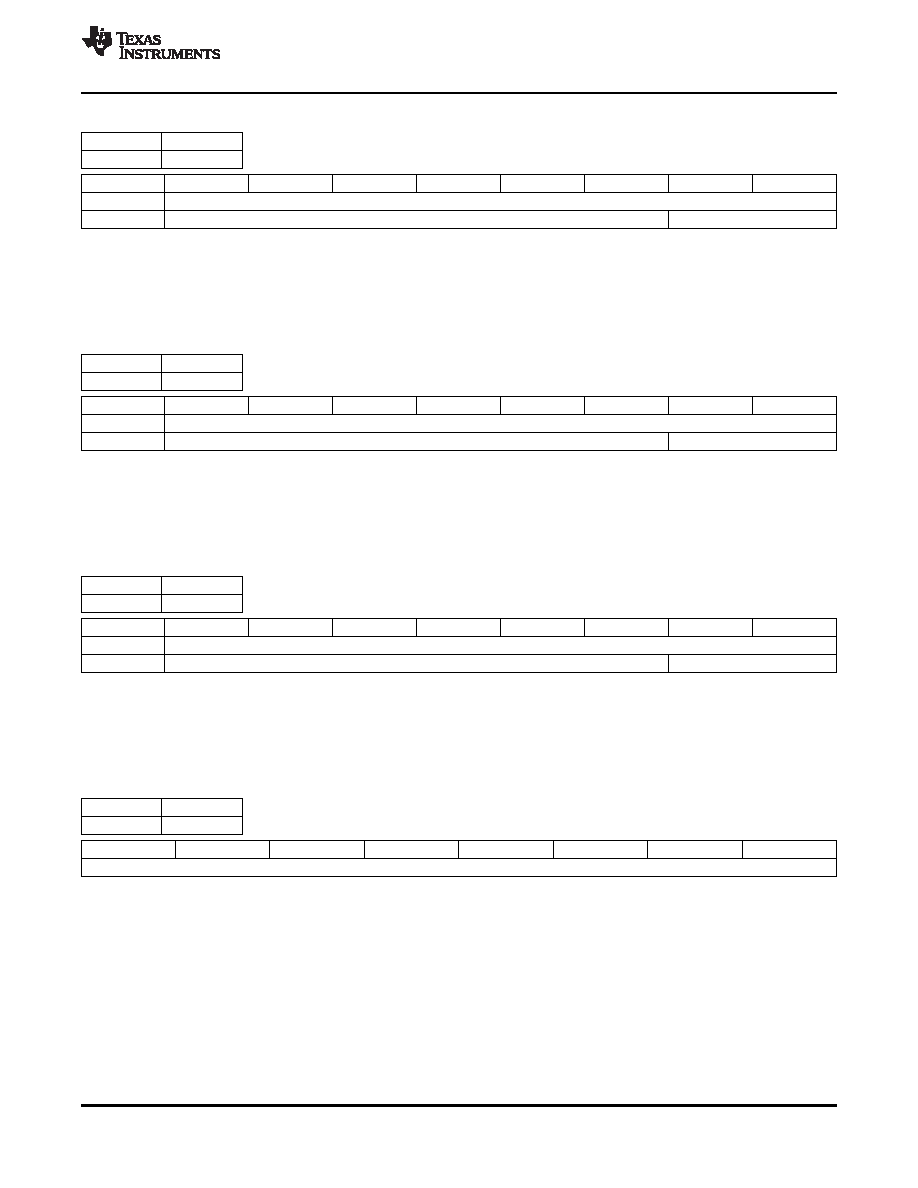
Table 3-28. VS Stop Line
Subaddress
20h
–21h
Default
004h/001h
Subaddress
7
6
5
4
3
2
1
0
20h
VS stop [7:0]
21h
Reserved
VS stop [9:8]
VS stop [9:0]: This is an absolute line number.
The TVP5160 decoder updates the VS stop only when the VS stop MSB byte is written to. If these registers are modified, then the
TVP5160 decoder retains the values for each video standard until the device is reset. The values for a particular video standard must be
set by forcing the decoder to the desired video standard first using register 02h then setting this register. This must be repeated for each
video standard where the default values need to be changed.
Table 3-29. VBLK Start Line
Subaddress
22h
–23h
Default
001h/26Fh
Subaddress
7
6
5
4
3
2
1
0
22h
VBLK start [7:0]
23h
Reserved
VBLK start [9:8]
VBLK start [9:0]: This is an absolute line number.
The TVP5160 decoder updates the VBLK start line only when the VBLK start MSB byte is written to. If these registers are modified, then
the TVP5160 decoder retains the values for each video standard until the device is reset. The values for a particular video standard must
be set by forcing the decoder to the desired video standard first using register 02h then setting this register. This must be repeated for each
video standard where the default values need to be changed.
Table 3-30. VBLK Stop Line
Subaddress
24h
–25h
Default
001h/26Fh
Subaddress
7
6
5
4
3
2
1
0
24h
VBLK stop [7:0]
25h
Reserved
VBLK stop [9:8]
VBLK stop [9:0]: This is an absolute line number.
The TVP5160 decoder updates the VBLK stop only when the VBLK stop MSB byte is written to. If these registers are modified, then the
TVP5160 decoder retains the values for each video standard until the device is reset. The values for a particular video standard must be
set by forcing the decoder to the desired video standard first using register 02h then setting this register. This must be repeated for each
video standard where the default values need to be changed.
Table 3-31. Embedded Sync Offset Control 1
Subaddress
26h
Default
00h
7
6
5
4
3
2
1
0
Offset [7:0]
This register allows the line position of the embedded F bit and V bit signals to be offset from the 656 standard positions. This register is
only applicable to input video signals with standard number of lines.
0111 1111 = 127 lines
0000 0001 = 1 line
0000 0000 = 0 line
1111 1111 =
–1 line
1000 0000 =
–128 lines
Copyright
2005–2011, Texas Instruments Incorporated
Internal Control Registers
53
focus.ti.com: TVP5160
相關(guān)PDF資料 |
PDF描述 |
|---|---|
| TVP5200PZP | SPECIALTY CONSUMER CIRCUIT, PQFP100 |
| TVP6000CPFP | COLOR SIGNAL ENCODER, PQFP80 |
| TVP7000PZPG4 | SPECIALTY CONSUMER CIRCUIT, PQFP100 |
| TVP7000PZPRG4 | SPECIALTY CONSUMER CIRCUIT, PQFP100 |
| TVP7000PZPR | SPECIALTY CONSUMER CIRCUIT, PQFP100 |
相關(guān)代理商/技術(shù)參數(shù) |
參數(shù)描述 |
|---|---|
| TVP5160PNPG4 | 制造商:Texas Instruments 功能描述: |
| TVP6000C | 制造商:TI 制造商全稱:Texas Instruments 功能描述:NTSC/PAL Digital Video Encoder |
| TVP6000CPFP | 功能描述:接口—CODEC NTSC / PAL VIDEO ENCODER RoHS:否 制造商:Texas Instruments 類型: 分辨率: 轉(zhuǎn)換速率:48 kSPs 接口類型:I2C ADC 數(shù)量:2 DAC 數(shù)量:4 工作電源電壓:1.8 V, 2.1 V, 2.3 V to 5.5 V 最大工作溫度:+ 85 C 安裝風(fēng)格:SMD/SMT 封裝 / 箱體:DSBGA-81 封裝:Reel |
| TVP7000 | 制造商:Texas Instruments 功能描述:Triple 8-bit Digitizer 150MSPS TVP7000 |
| TVP7000EVM | 功能描述:視頻 IC 開(kāi)發(fā)工具 TVP7000 Eval Mod RoHS:否 制造商:Texas Instruments 產(chǎn)品:Evaluation Boards 類型:YPbPr to RGBHV Converters 工具用于評(píng)估:LMH1251 工作電源電壓:5 V |
發(fā)布緊急采購(gòu),3分鐘左右您將得到回復(fù)。