- 您現(xiàn)在的位置:買賣IC網(wǎng) > PDF目錄98306 > TVP5160PNP (TEXAS INSTRUMENTS INC) COLOR SIGNAL DECODER, PQFP128 PDF資料下載
參數(shù)資料
| 型號(hào): | TVP5160PNP |
| 廠商: | TEXAS INSTRUMENTS INC |
| 元件分類: | 顏色信號(hào)轉(zhuǎn)換 |
| 英文描述: | COLOR SIGNAL DECODER, PQFP128 |
| 封裝: | GREEN, PLASTIC, HTQFP-128 |
| 文件頁數(shù): | 29/111頁 |
| 文件大?。?/td> | 1400K |
| 代理商: | TVP5160PNP |
第1頁第2頁第3頁第4頁第5頁第6頁第7頁第8頁第9頁第10頁第11頁第12頁第13頁第14頁第15頁第16頁第17頁第18頁第19頁第20頁第21頁第22頁第23頁第24頁第25頁第26頁第27頁第28頁當(dāng)前第29頁第30頁第31頁第32頁第33頁第34頁第35頁第36頁第37頁第38頁第39頁第40頁第41頁第42頁第43頁第44頁第45頁第46頁第47頁第48頁第49頁第50頁第51頁第52頁第53頁第54頁第55頁第56頁第57頁第58頁第59頁第60頁第61頁第62頁第63頁第64頁第65頁第66頁第67頁第68頁第69頁第70頁第71頁第72頁第73頁第74頁第75頁第76頁第77頁第78頁第79頁第80頁第81頁第82頁第83頁第84頁第85頁第86頁第87頁第88頁第89頁第90頁第91頁第92頁第93頁第94頁第95頁第96頁第97頁第98頁第99頁第100頁第101頁第102頁第103頁第104頁第105頁第106頁第107頁第108頁第109頁第110頁第111頁
SLES135E
– FEBRUARY 2005 – REVISED APRIL 2011
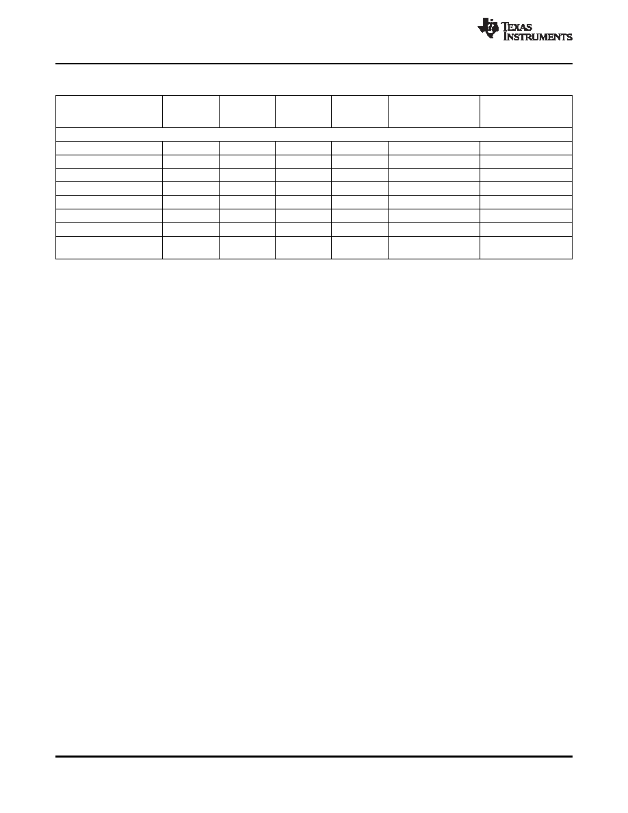
Table 2-3. Summary of Line Frequency, Data Rate, and Pixel/Line Counts
ACTIVE
COLOR
PIXELS
LINES PER
PIXEL FREQ
HORIZONTAL
STANDARDS
PIXELS
SUBCARRIER
PER LINE
FRAME
(MHz)
LINE RATE (kHz)
PER LINE
FREQUENCY (MHz)
ITU-R BT.601 sampling
NTSC-J, M
858
720
525
13.5
3.579545
15.73426
NTSC-4.43
858
720
525
13.5
4.43361875
15.73426
PAL-M
858
720
525
13.5
3.57561149
15.73426
PAL-60
858
720
525
13.5
4.43361875
15.73426
PAL-B, D, G, H, I
864
720
625
13.5
4.43361875
15.625
PAL-N
864
720
625
13.5
4.43361875
15.625
PAL-Nc
864
720
625
13.5
3.58205625
15.625
Dr = 4.406250
SECAM
864
720
625
13.5
15.625
Db = 4.250000
The TVP5160 input-to-output processing delay depends on the operating mode and the video standard.
When 3DYC is enabled, the processing delay is approximately 1 frame and 2-1/3 lines. When 3DYC is
disabled, the processing delay is approximately 2-1/3 lines.
2.6
Fast Switches for SCART and Digital Overlay
The TVP5160 decoder supports the SCART interface used mainly in European audio/video end
equipment to carry mono/stereo audio, composite video, S-Video, and RGB video on the same cable. In
the event that composite video and RGB video are present simultaneously on the video pins assigned to a
SCART interface, the TVP5160 decoder assumes they are pixel synchronous to each other. The timing for
both composite video and RGB video is obtained from the composite source and its derived clock is used
to sample RGB video as well. The fast-switch input pin allows switching between these two input video
sources on a pixel-by-pixel basis. This feature can be used to, for example, overlay RGB graphics for
on-screen display onto decoded CVBS video. The SCART overlay control signals (FSS) are oversampled
at 4
× the pixel clock frequency. The phase of this signal is used to mix between the CVBS input and the
analog RGB inputs. This improves the analog overlay picture quality when the external FSS and analog
video signals are generated by an asynchronous source. The TVP5160 decoder has two programmable
delays for component video to compensate for composite comb filter delays and two programmable delays
for digital RGB to compensate AFE and decimation filter delays.
If the overlay output is digital supporting 8 colors of data, the TVP5160 decoder can take digital overlay
inputs using terminals C6, C7, and C8. For this mode, output must be the 10-bit ITU-R BT.656 mode.
Figure 2-6 shows the block diagram of two fast-switches. Table 2-4 shows the fast-switch 1 and 2
controls.
24
Functional Description
Copyright
2005–2011, Texas Instruments Incorporated
focus.ti.com: TVP5160
相關(guān)PDF資料 |
PDF描述 |
|---|---|
| TVP5200PZP | SPECIALTY CONSUMER CIRCUIT, PQFP100 |
| TVP6000CPFP | COLOR SIGNAL ENCODER, PQFP80 |
| TVP7000PZPG4 | SPECIALTY CONSUMER CIRCUIT, PQFP100 |
| TVP7000PZPRG4 | SPECIALTY CONSUMER CIRCUIT, PQFP100 |
| TVP7000PZPR | SPECIALTY CONSUMER CIRCUIT, PQFP100 |
相關(guān)代理商/技術(shù)參數(shù) |
參數(shù)描述 |
|---|---|
| TVP5160PNPG4 | 制造商:Texas Instruments 功能描述: |
| TVP6000C | 制造商:TI 制造商全稱:Texas Instruments 功能描述:NTSC/PAL Digital Video Encoder |
| TVP6000CPFP | 功能描述:接口—CODEC NTSC / PAL VIDEO ENCODER RoHS:否 制造商:Texas Instruments 類型: 分辨率: 轉(zhuǎn)換速率:48 kSPs 接口類型:I2C ADC 數(shù)量:2 DAC 數(shù)量:4 工作電源電壓:1.8 V, 2.1 V, 2.3 V to 5.5 V 最大工作溫度:+ 85 C 安裝風(fēng)格:SMD/SMT 封裝 / 箱體:DSBGA-81 封裝:Reel |
| TVP7000 | 制造商:Texas Instruments 功能描述:Triple 8-bit Digitizer 150MSPS TVP7000 |
| TVP7000EVM | 功能描述:視頻 IC 開發(fā)工具 TVP7000 Eval Mod RoHS:否 制造商:Texas Instruments 產(chǎn)品:Evaluation Boards 類型:YPbPr to RGBHV Converters 工具用于評(píng)估:LMH1251 工作電源電壓:5 V |
發(fā)布緊急采購,3分鐘左右您將得到回復(fù)。