- 您現(xiàn)在的位置:買賣IC網(wǎng) > PDF目錄384010 > TLV5592 (Texas Instruments, Inc.) 2-BIT ANALOG-TO-DIGITAL CONVERTER FOR FLEX PAGER CHIPSET PDF資料下載
參數(shù)資料
| 型號(hào): | TLV5592 |
| 廠商: | Texas Instruments, Inc. |
| 英文描述: | 2-BIT ANALOG-TO-DIGITAL CONVERTER FOR FLEX PAGER CHIPSET |
| 中文描述: | 2位模擬數(shù)字轉(zhuǎn)換器對(duì)于Flex尋呼機(jī)芯片組 |
| 文件頁數(shù): | 9/15頁 |
| 文件大小: | 208K |
| 代理商: | TLV5592 |
TLV5592
2-BIT ANALOG-TO-DIGITAL CONVERTER
FOR FLEX PAGER CHIPSET
SLAS145A – JUNE1996 – REVISED DECEMBER 1997
9
POST OFFICE BOX 655303
DALLAS, TEXAS 75265
PRINCIPLES OF OPERATION
digital control
Five digital inputs and the CLK input control the TLV5592. The five signals are BW, CON1, CON2, TRACKINH
and TEST. All digital control inputs are latched internally on the falling edge of the CLK input. The BW input
selects the cutoff frequency of the input signal third-order Butterworth switched-capacitor filter. The CON1 and
CON2 inputs determine when the TLV5592 is in tracking fast, tracking slow, hold, or low-power standby mode.
In test mode the CLK input is level sensitive, and in all other modes the CLK input is edge sensitive.
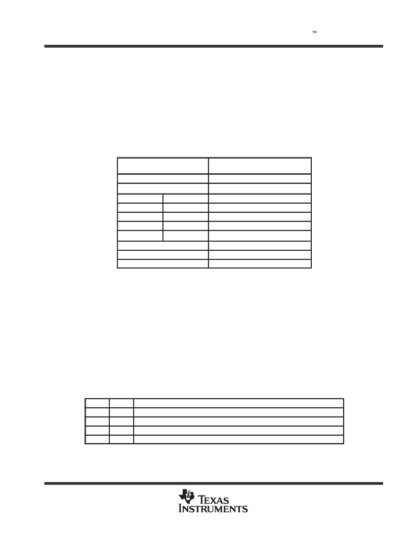
Table 1 lists the functions for the five control inputs.
Table 1. Control Inputs Function Table
BW
SWITCHED-CAPACITOR FILTER
(– 3 dB POINT)
Low
1-kHz filter cutoff
High
2-kHz filter cutoff
CON1
CON2
MODE
Low
Low
Low-power standby (off) mode
Low
High
Fast track mode
High
Low
Hold mode
High
High
Slow track mode
TRACKINH
RESULT
Low
Tracking enabled
High
Tracking disabled
track inhibit
The TRACKINH input enables the counters to the peak and valley detector DACs. When enabled, the counters
adjust to create a DAC output that is the same as the filtered input signal peak and valley. The counters decay
at the fast or slow decay rates while the TRACKINH input is held low. The TRACKINH line should be connected
to SYMCLK terminal on the TLV559X decoder.
analog-to-digital conversion
The TLV5592 employs a 2-bit ADC to convert a 4-level analog signal to digital data. The digital output is
presented on EXTS0 and EXTS1 with EXTS0 being the LSB. The peak and valley DACs provide the maximum
and minimum voltages (V
ref+
and V
ref–
) to the ADC. The input to the 2-bit ADC is the output of the Butterworth
low-pass filter, FILOUT, as shown in the block diagram. The ADC transfer function is shown in Table 2.
Table 2. Filter Output Voltage Selection (see Note 4)
EXTS1
Low
EXTS0
Low
FILTER OUTPUT VOLTAGE (FILOUT)
FILOUT < ((peak – valley) x 50/256) + valley
High
Low
((peak – valley) x 50/256) + valley < FILOUT < ((peak – valley) x 134/256) + valley
High
High
((peak – valley) x 134/256) + valley < FILOUT < (( peak – valley) x 217/256) + valley
Low
High
FILOUT > ((peak – valley) x 217/256) + valley
NOTE 4: The constants 50/256, 134/256, and 217/256 have a
±
5% tolerance.
相關(guān)PDF資料 |
PDF描述 |
|---|---|
| TLV5592D | 2-BIT ANALOG-TO-DIGITAL CONVERTER FOR FLEX PAGER CHIPSET |
| TLV5604D | 2.7-V TO 5.5-V 10-BIT 3-mS QUADRUPLE DIGITAL-TO-ANALOG CONVERTERS WITH POWER DOWN |
| TLV5604PW | 2.7-V TO 5.5-V 10-BIT 3-mS QUADRUPLE DIGITAL-TO-ANALOG CONVERTERS WITH POWER DOWN |
| TLV5606D | 2.7 V TO 5.5 V LOW POWER 10-BIT DIGITAL-TO-ANALOG CONVERTERS WITH POWER DOWN |
| TLV5606DGK | 2.7 V TO 5.5 V LOW POWER 10-BIT DIGITAL-TO-ANALOG CONVERTERS WITH POWER DOWN |
相關(guān)代理商/技術(shù)參數(shù) |
參數(shù)描述 |
|---|---|
| TLV5592D | 制造商:TI 制造商全稱:Texas Instruments 功能描述:2-BIT ANALOG-TO-DIGITAL CONVERTER FOR FLEX PAGER CHIPSET |
| TLV5592ED | 制造商:Texas Instruments 功能描述: |
| TLV5592EDR | 制造商:Texas Instruments 功能描述: |
| TLV5592EPWR | 制造商:Texas Instruments 功能描述:1.8 VOLT 2-BIT FLOATING ADC FOR FLEX PAGER CHIPSET - Tape and Reel |
| TLV5593VF | 制造商:Rochester Electronics LLC 功能描述:- Bulk 制造商:Texas Instruments 功能描述:5593VF |
發(fā)布緊急采購,3分鐘左右您將得到回復(fù)。