- 您現(xiàn)在的位置:買賣IC網(wǎng) > PDF目錄384010 > TLV5592 (Texas Instruments, Inc.) 2-BIT ANALOG-TO-DIGITAL CONVERTER FOR FLEX PAGER CHIPSET PDF資料下載
參數(shù)資料
| 型號: | TLV5592 |
| 廠商: | Texas Instruments, Inc. |
| 英文描述: | 2-BIT ANALOG-TO-DIGITAL CONVERTER FOR FLEX PAGER CHIPSET |
| 中文描述: | 2位模擬數(shù)字轉(zhuǎn)換器對于Flex尋呼機芯片組 |
| 文件頁數(shù): | 8/15頁 |
| 文件大小: | 208K |
| 代理商: | TLV5592 |
TLV5592
2-BIT ANALOG-TO-DIGITAL CONVERTER
FOR FLEX PAGER CHIPSET
SLAS145A – JUNE1996 – REVISED DECEMBER 1997
8
POST OFFICE BOX 655303
DALLAS, TEXAS 75265
PRINCIPLES OF OPERATION
analog input operation
As shown in the functional block diagram, the signal input is dc-coupled using a single input terminal, SIG. A
voltage equivalent to the nominal dc voltage of the signal input at SIG should be supplied on an additional
terminal, DC OFFSET. This allows the device to increase the signal to acceptable levels for threshold detection
without saturating against the supplies. The signal processed by the device is effectively the voltage difference
between the SIG and DC OFFSET terminals.
There is no antialiasing filter incorporated in the device. TI recommends that an external RC filter be added and
set at the appropriate cutoff (see Figure 5).
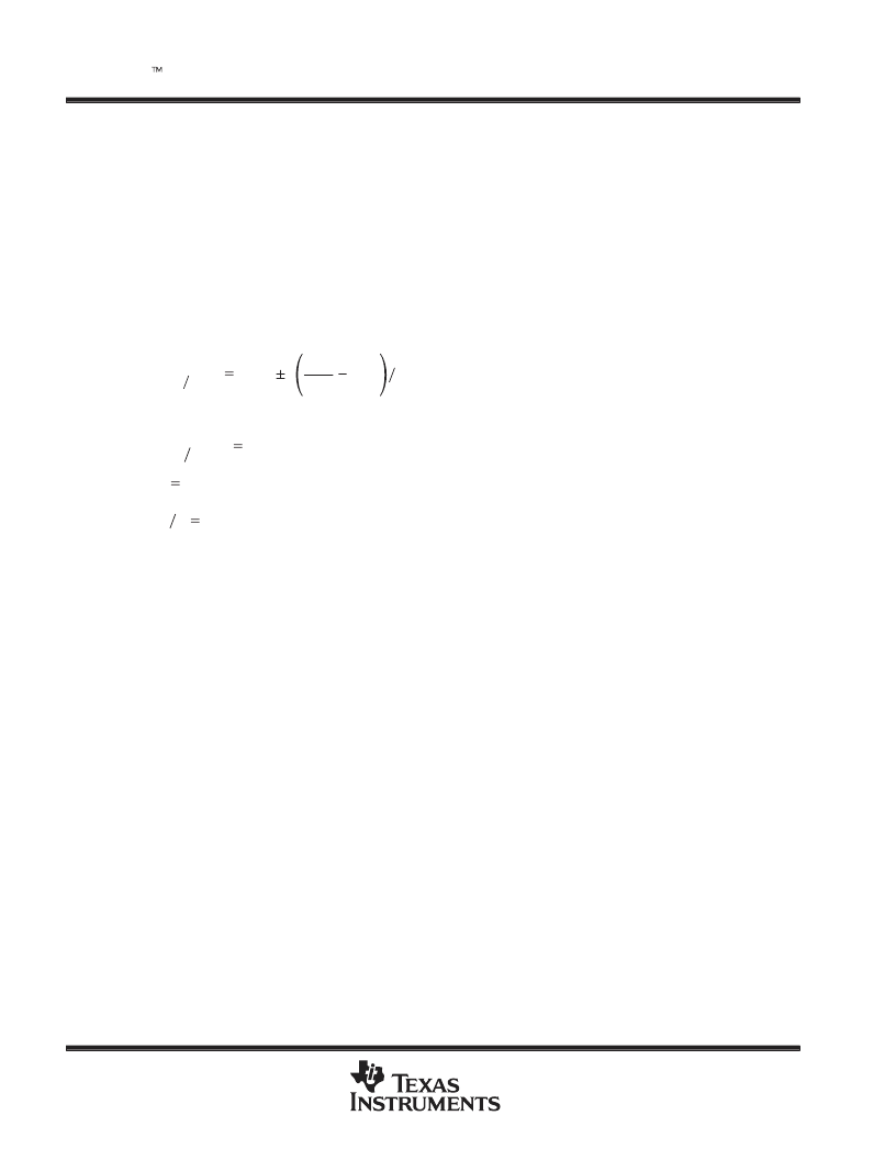
The maximum peak analog signal voltage that can be applied to the SIG input terminal is given by:
V
I(MAX MIN)
V
IO
VDD
2
0.25
(
FILTER MAX GAIN)
where:
VDD2
the nominal output voltage at the MID terminal
VI(MIN MAX)
Analog input voltage (SIG)
VIO
Input offset voltage (dc offset)
The main signal path consists of a third-order switched-capacitor Butterworth filter, with a bandwidth that is
switchable between 1 kHz and 2 kHz to remove the noise from the input signal. The peak and valley amplitudes
of the filter output signal are detected and subsequently used to convert the 4-level audio into 2-level digital
signals using three switched capacitor comparators.
digital operation
The peak and valley detection is performed by a mixed mode solution using an 8-bit DAC and an up/down
counter that has nonsymmetrical up and down count rates. Various modes are included to force the peak and
valley circuits to slow track, fast track, or hold. An off mode is included that forces the device into a low-power
condition. The decay rate of the peak and valley circuits is controlled by independent counters.
The device is clocked with a 38.4-kHz square wave supplied externally. The attack and decay times of the peak
and valley circuits and the filter cutoff frequencies are directly related to this clock frequency. The decay timer
is gated by the track inhibit input, TRACKINH, which is reset to 1 after an attack occurs and reset to 40 after
a decay enable. The TRACKINH also prevents attack enable inputs from affecting the peak and valley counters.
相關(guān)PDF資料 |
PDF描述 |
|---|---|
| TLV5592D | 2-BIT ANALOG-TO-DIGITAL CONVERTER FOR FLEX PAGER CHIPSET |
| TLV5604D | 2.7-V TO 5.5-V 10-BIT 3-mS QUADRUPLE DIGITAL-TO-ANALOG CONVERTERS WITH POWER DOWN |
| TLV5604PW | 2.7-V TO 5.5-V 10-BIT 3-mS QUADRUPLE DIGITAL-TO-ANALOG CONVERTERS WITH POWER DOWN |
| TLV5606D | 2.7 V TO 5.5 V LOW POWER 10-BIT DIGITAL-TO-ANALOG CONVERTERS WITH POWER DOWN |
| TLV5606DGK | 2.7 V TO 5.5 V LOW POWER 10-BIT DIGITAL-TO-ANALOG CONVERTERS WITH POWER DOWN |
相關(guān)代理商/技術(shù)參數(shù) |
參數(shù)描述 |
|---|---|
| TLV5592D | 制造商:TI 制造商全稱:Texas Instruments 功能描述:2-BIT ANALOG-TO-DIGITAL CONVERTER FOR FLEX PAGER CHIPSET |
| TLV5592ED | 制造商:Texas Instruments 功能描述: |
| TLV5592EDR | 制造商:Texas Instruments 功能描述: |
| TLV5592EPWR | 制造商:Texas Instruments 功能描述:1.8 VOLT 2-BIT FLOATING ADC FOR FLEX PAGER CHIPSET - Tape and Reel |
| TLV5593VF | 制造商:Rochester Electronics LLC 功能描述:- Bulk 制造商:Texas Instruments 功能描述:5593VF |
發(fā)布緊急采購,3分鐘左右您將得到回復(fù)。