- 您現(xiàn)在的位置:買賣IC網(wǎng) > PDF目錄383957 > TLV320AIC3106_0706 (Texas Instruments, Inc.) LOW-POWER STEREO AUDIO CODEC FOR PORTABLE AUDIO/TELEPHONY PDF資料下載
參數(shù)資料
| 型號: | TLV320AIC3106_0706 |
| 廠商: | Texas Instruments, Inc. |
| 元件分類: | Codec |
| 英文描述: | LOW-POWER STEREO AUDIO CODEC FOR PORTABLE AUDIO/TELEPHONY |
| 中文描述: | 低功耗立體聲音頻編解碼器的便攜式音頻/電話 |
| 文件頁數(shù): | 31/102頁 |
| 文件大小: | 1259K |
| 代理商: | TLV320AIC3106_0706 |
第1頁第2頁第3頁第4頁第5頁第6頁第7頁第8頁第9頁第10頁第11頁第12頁第13頁第14頁第15頁第16頁第17頁第18頁第19頁第20頁第21頁第22頁第23頁第24頁第25頁第26頁第27頁第28頁第29頁第30頁當前第31頁第32頁第33頁第34頁第35頁第36頁第37頁第38頁第39頁第40頁第41頁第42頁第43頁第44頁第45頁第46頁第47頁第48頁第49頁第50頁第51頁第52頁第53頁第54頁第55頁第56頁第57頁第58頁第59頁第60頁第61頁第62頁第63頁第64頁第65頁第66頁第67頁第68頁第69頁第70頁第71頁第72頁第73頁第74頁第75頁第76頁第77頁第78頁第79頁第80頁第81頁第82頁第83頁第84頁第85頁第86頁第87頁第88頁第89頁第90頁第91頁第92頁第93頁第94頁第95頁第96頁第97頁第98頁第99頁第100頁第101頁第102頁
www.ti.com
AUTOMATIC GAIN CONTROL (AGC)
An automatic gain control (AGC) circuit is included with the ADC and can be used to maintain nominally
constant output signal amplitude when recording speech signals (it can be fully disabled if not desired). This
circuitry automatically adjusts the PGA gain as the input signal becomes overly loud or very weak, such as when
a person speaking into a microphone moves closer or farther from the microphone. The AGC algorithm has
several programmable settings, including target gain, attack and decay time constants, noise threshold, and
maximum PGA gain applicable that allow the algorithm to be fine tuned for any particular application. The
algorithm uses the absolute average of the signal (which is the average of the absolute value of the signal) as a
measure of the nominal amplitude of the output signal.
TLV320AIC3106
SLAS509B–DECEMBER 2006–REVISED JUNE 2007
Note that completely independent AGC circuitry is included with each ADC channel with entirely independent
control over the algorithm from one channel to the next. This is attractive in cases where two microphones are
used in a system, but may have different placement in the end equipment and require different dynamic
performance for optimal system operation.
Target level
represents the nominal output level at which the AGC attempts to hold the ADC output signal level.
The TLV320AIC3106 allows programming of eight different target levels, which can be programmed from –5.5
dB to –24 dB relative to a full-scale signal. Since the device reacts to the signal absolute average and not to
peak levels, it is recommended that the target level be set with enough margin to avoid clipping at the
occurrence of loud sounds.
Attack time
determines how quickly the AGC circuitry reduces the PGA gain when the input signal is too loud. It
can be varied from 7 ms to 1,408 ms. The extended Right Channel Attack time can be programmed by writing to
Page 0, Registers 103, and Left Channel is programmed by writing to Page 0, Register 105.
Decay time
determines how quickly the PGA gain is increased when the input signal is too low. It can be varied
in the range from 0.05 s to 22.4 s. The extended Right Channel Decay time can be programmed by writing to
Page 0, Registers 104, and Left Channel is programmed by writing to Page 0, Register 106.
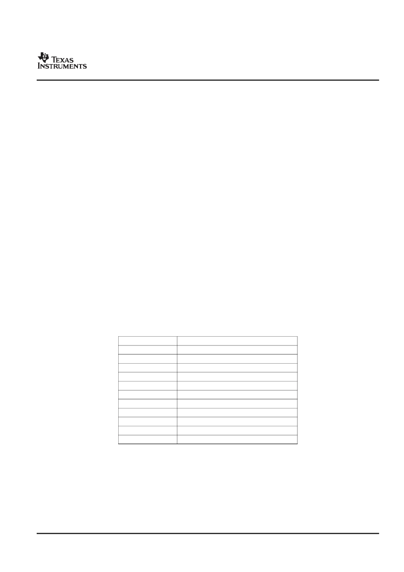
The actual AGC decay time maximum is based on a counter length, so the maximum decay time will scale with
the clock set up that is used. The table below shows the relationship of the NADC ratio to the maximum time
available for the AGC decay. In practice, these maximum times are extremely long for audio applications and
should not limit any practical AGC decay time that is needed by the system.
Table 1. AGC Decay Time Restriction
NADC RATIO
1.0
1.5
2.0
2.5
3.0
3.5
4.0
4.5
5.0
5.5
6.0
MAXIMUM DECAY TIME (seconds)
4.0
5.6
8.0
9.6
11.2
11.2
16.0
16.0
19.2
22.4
22.4
Noise gate threshold
determines the level below which if the input speech average value falls, AGC considers
it as a silence and hence brings down the gain to 0 dB in steps of 0.5 dB every FS and sets the noise threshold
flag. The gain stays at 0 dB unless the input speech signal average rises above the noise threshold setting. This
ensures that noise does not get gained up in the absence of speech. Noise threshold level in the AGC algorithm
is programmable from –30 dB to –90 dB relative to full scale. A disable noise gate feature is also available. This
operation includes programmable debounce and hysteresis functionality to avoid the AGC gain from cycling
between high gain and 0 dB when signals are near the noise threshold level. When the noise threshold flag is
set, the status of gain applied by the AGC and the saturation flag should be ignored.
31
Submit Documentation Feedback
相關(guān)PDF資料 |
PDF描述 |
|---|---|
| TLV320AIC3106IGQE | LOW-POWER STEREO AUDIO CODEC FOR PORTABLE AUDIO/TELEPHONY |
| TLV320AIC3106IGQER | LOW-POWER STEREO AUDIO CODEC FOR PORTABLE AUDIO/TELEPHONY |
| TLV341_07 | LOW-VOLTAGE RAIL-TO-RAIL OUTPUT CMOS OPERATIONAL AMPLIFLERS WITH SHUTDOWN |
| TLV431ACDBV | LOW-VOLTAGE ADJUSTABLE PRECISION SHUNT REGULATORS |
| TLV431ID | LOW-VOLTAGE ADJUSTABLE PRECISION SHUNT REGULATORS |
相關(guān)代理商/技術(shù)參數(shù) |
參數(shù)描述 |
|---|---|
| TLV320AIC3106EVM | 功能描述:音頻 IC 開發(fā)工具 TLV320AIC3106 Eval Mod RoHS:否 制造商:Texas Instruments 產(chǎn)品:Evaluation Kits 類型:Audio Amplifiers 工具用于評估:TAS5614L 工作電源電壓:12 V to 38 V |
| TLV320AIC3106EVM-K | 功能描述:音頻 IC 開發(fā)工具 TLV320AIC3106EVM-K Eval Mod RoHS:否 制造商:Texas Instruments 產(chǎn)品:Evaluation Kits 類型:Audio Amplifiers 工具用于評估:TAS5614L 工作電源電壓:12 V to 38 V |
| TLV320AIC3106IGQE | 制造商:Texas Instruments 功能描述:AUD CODEC 2ADC / 2DAC 24BIT 80BGA - Trays |
| TLV320AIC3106IGQER | 制造商:Texas Instruments 功能描述:AUD CODEC 2ADC / 2DAC 24BIT 80BGA - Tape and Reel |
| TLV320AIC3106IRGZR | 功能描述:接口—CODEC Lo-Pwr Stereo CODEC RoHS:否 制造商:Texas Instruments 類型: 分辨率: 轉(zhuǎn)換速率:48 kSPs 接口類型:I2C ADC 數(shù)量:2 DAC 數(shù)量:4 工作電源電壓:1.8 V, 2.1 V, 2.3 V to 5.5 V 最大工作溫度:+ 85 C 安裝風格:SMD/SMT 封裝 / 箱體:DSBGA-81 封裝:Reel |
發(fā)布緊急采購,3分鐘左右您將得到回復(fù)。