- 您現(xiàn)在的位置:買賣IC網(wǎng) > PDF目錄383878 > TAS5028APAG (Texas Instruments, Inc.) 8 Channel Digital Audio PWM Processor PDF資料下載
參數(shù)資料
| 型號(hào): | TAS5028APAG |
| 廠商: | Texas Instruments, Inc. |
| 英文描述: | 8 Channel Digital Audio PWM Processor |
| 中文描述: | 8通道數(shù)字音頻PWM處理器 |
| 文件頁(yè)數(shù): | 52/82頁(yè) |
| 文件大小: | 1226K |
| 代理商: | TAS5028APAG |
第1頁(yè)第2頁(yè)第3頁(yè)第4頁(yè)第5頁(yè)第6頁(yè)第7頁(yè)第8頁(yè)第9頁(yè)第10頁(yè)第11頁(yè)第12頁(yè)第13頁(yè)第14頁(yè)第15頁(yè)第16頁(yè)第17頁(yè)第18頁(yè)第19頁(yè)第20頁(yè)第21頁(yè)第22頁(yè)第23頁(yè)第24頁(yè)第25頁(yè)第26頁(yè)第27頁(yè)第28頁(yè)第29頁(yè)第30頁(yè)第31頁(yè)第32頁(yè)第33頁(yè)第34頁(yè)第35頁(yè)第36頁(yè)第37頁(yè)第38頁(yè)第39頁(yè)第40頁(yè)第41頁(yè)第42頁(yè)第43頁(yè)第44頁(yè)第45頁(yè)第46頁(yè)第47頁(yè)第48頁(yè)第49頁(yè)第50頁(yè)第51頁(yè)當(dāng)前第52頁(yè)第53頁(yè)第54頁(yè)第55頁(yè)第56頁(yè)第57頁(yè)第58頁(yè)第59頁(yè)第60頁(yè)第61頁(yè)第62頁(yè)第63頁(yè)第64頁(yè)第65頁(yè)第66頁(yè)第67頁(yè)第68頁(yè)第69頁(yè)第70頁(yè)第71頁(yè)第72頁(yè)第73頁(yè)第74頁(yè)第75頁(yè)第76頁(yè)第77頁(yè)第78頁(yè)第79頁(yè)第80頁(yè)第81頁(yè)第82頁(yè)
I
2
C Serial Control Interface (Slave Address 0x36)
45
SLES120
September 2004
TAS5028A
4
I
2
C Serial Control Interface (Slave Address 0x36)
The TAS5028A has a bidirectional I
2
C interface that compatible with the I
2
C (Inter IC) bus protocol and
supports both 100 Kbps and 400 Kbps data transfer rates for single
and multiple
write and read operations.
This is a slave only device that does not support a multi-master bus environment or wait state insertion. The
control interface is used to program the registers of the device and to read device status.
The TAS5028A supports the standard-mode I
2
C bus operation (100 kHz maximum) and the fast I
2
C bus
operation (400 kHz maximum). The TAS5028A performs all I
2
C operations without I
2
C wait cycles.
General I
2
C Operation
The I
2
C bus employs two signals; SDA (data) and SCL (clock), to communicate between integrated circuits
in a system. Data is transferred on the bus serially one bit at a time. The address and data can be transferred
in byte (8 bit) format, with the most significant bit (MSB) transferred first. In addition, each byte transferred on
the bus is acknowledged by the receiving device with an acknowledge bit. Each transfer operation begins with
the master device driving a start condition on the bus and ends with the master device driving a stop condition
on the bus. The bus uses transitions on the data terminal (SDA) while the clock is high to indicate a start and
stop conditions. A high-to-low transition on SDA indicates a start and a low-to-high transition indicates a stop.
Normal data bit transitions must occur within the low time of the clock period. These conditions are shown in
Figure 4
1. The master generates the 7-bit slave address and the read/write (R/W) bit to open communication
with another device and then wait for an acknowledge condition. The TAS5028A holds SDA low during
acknowledge clock period to indicate an acknowledgement. When this occurs, the master transmits the next
byte of the sequence. Each device is addressed by a unique 7-bit slave address plus R/W bit (1 byte). All
compatible devices share the same signals via a bidirectional bus using a wired-AND connection. An external
pullup resistor must be used for the SDA and SCL signals to set the high level for the bus.
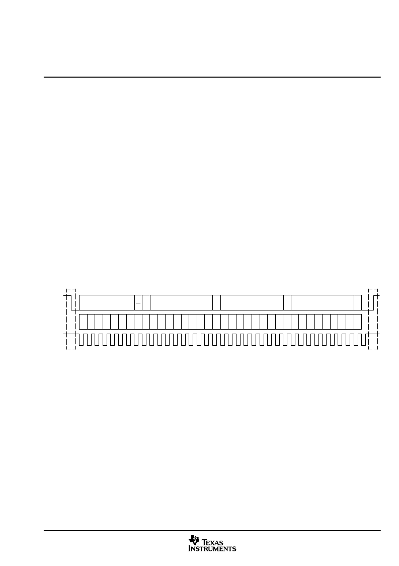
4.1
7 Bit Slave Address
R/
W
8 Bit Register Address (N)
A
8 Bit Register Data For
Address (N)
Start
Stop
SDA
SCL
7
6
5
4
3
2
1
0
7
6
5
4
3
2
1
0
A
7
6
5
4
3
2
1
0
8 Bit Register Data For
Address (N)
7
6
5
4
3
2
1
0
A
A
Figure 4
1. Typical I
2
C Sequence
There is no limit on the number of bytes that can be transmitted between start and stop conditions. When the
last word transfers, the master generates a stop condition to release the bus. A generic data transfer sequence
is shown in Figure 4
1.
The 7-bit address for the TAS5028A is 0011011.
4.2
Single
and Multiple
Byte Transfers
The serial control interface supports both single
byte and multiple
byte read/write operations for status
registers and the general control registers associated with the PWM. However, for the DAP data processing
registers, the serial control interface supports only multiple
byte (4 bytes) read/write operations.
During multiple
byte read operations, the TAS5028A responds with data, a byte at a time, starting at the
subaddress assigned, as long as the master device continues to respond with acknowledges. If a particular
subaddress does not contain 32 bits, the unused bits are read as logic 0.
During multiple
byte write operations, the TAS5028A compares the number of bytes transmitted to the
number of bytes that are required for each specific sub address. If a write command is received for a mixer
coefficient, the TAS5028A expects to receive one 32-bit word. If fewer than 32 bits are required when a stop
command (or another start command) is received, the data received is discarded.
相關(guān)PDF資料 |
PDF描述 |
|---|---|
| TAS5028APAGG4 | 8 Channel Digital Audio PWM Processor |
| TAS5028APAGR | 8 Channel Digital Audio PWM Processor |
| TAS5028APAGRG4 | 8 Channel Digital Audio PWM Processor |
| TAS5028PAGR | 8 Channel Digital Audio PWM Processor |
| TAS5028PAGRG4 | 8 Channel Digital Audio PWM Processor |
相關(guān)代理商/技術(shù)參數(shù) |
參數(shù)描述 |
|---|---|
| TAS5028APAGG4 | 功能描述:音頻放大器 8Ch Dig Aud PWM Proc RoHS:否 制造商:STMicroelectronics 產(chǎn)品:General Purpose Audio Amplifiers 輸出類型:Digital 輸出功率: THD + 噪聲: 工作電源電壓:3.3 V 電源電流: 最大功率耗散: 最大工作溫度: 安裝風(fēng)格:SMD/SMT 封裝 / 箱體:TQFP-64 封裝:Reel |
| TAS5028APAGR | 功能描述:音頻放大器 8Ch Dig Aud PWM Proc RoHS:否 制造商:STMicroelectronics 產(chǎn)品:General Purpose Audio Amplifiers 輸出類型:Digital 輸出功率: THD + 噪聲: 工作電源電壓:3.3 V 電源電流: 最大功率耗散: 最大工作溫度: 安裝風(fēng)格:SMD/SMT 封裝 / 箱體:TQFP-64 封裝:Reel |
| TAS5028APAGRG4 | 功能描述:音頻放大器 8Ch Dig Aud PWM Proc RoHS:否 制造商:STMicroelectronics 產(chǎn)品:General Purpose Audio Amplifiers 輸出類型:Digital 輸出功率: THD + 噪聲: 工作電源電壓:3.3 V 電源電流: 最大功率耗散: 最大工作溫度: 安裝風(fēng)格:SMD/SMT 封裝 / 箱體:TQFP-64 封裝:Reel |
| TAS5028PAG | 功能描述:音頻 DSP 8 Ch Digital Audio PWM Processor RoHS:否 制造商:Texas Instruments 工作電源電壓: 電源電流: 工作溫度范圍: 安裝風(fēng)格: 封裝 / 箱體: 封裝:Tube |
| TAS5028PAGG4 | 功能描述:音頻 DSP 8 Ch Digital Audio PWM Processor RoHS:否 制造商:Texas Instruments 工作電源電壓: 電源電流: 工作溫度范圍: 安裝風(fēng)格: 封裝 / 箱體: 封裝:Tube |
發(fā)布緊急采購(gòu),3分鐘左右您將得到回復(fù)。