- 您現(xiàn)在的位置:買賣IC網(wǎng) > PDF目錄44996 > LTC4110EUHF#TR (LINEAR TECHNOLOGY CORP) 1-CHANNEL POWER SUPPLY SUPPORT CKT, PQCC38 PDF資料下載
參數(shù)資料
| 型號(hào): | LTC4110EUHF#TR |
| 廠商: | LINEAR TECHNOLOGY CORP |
| 元件分類: | 電源管理 |
| 英文描述: | 1-CHANNEL POWER SUPPLY SUPPORT CKT, PQCC38 |
| 封裝: | 5 X 7 MM, 0.75 MM HEIGHT, PLASTIC, MO-220WHKD, QFN-38 |
| 文件頁數(shù): | 39/52頁 |
| 文件大?。?/td> | 450K |
| 代理商: | LTC4110EUHF#TR |
第1頁第2頁第3頁第4頁第5頁第6頁第7頁第8頁第9頁第10頁第11頁第12頁第13頁第14頁第15頁第16頁第17頁第18頁第19頁第20頁第21頁第22頁第23頁第24頁第25頁第26頁第27頁第28頁第29頁第30頁第31頁第32頁第33頁第34頁第35頁第36頁第37頁第38頁當(dāng)前第39頁第40頁第41頁第42頁第43頁第44頁第45頁第46頁第47頁第48頁第49頁第50頁第51頁第52頁
LTC4110
44
4110fb
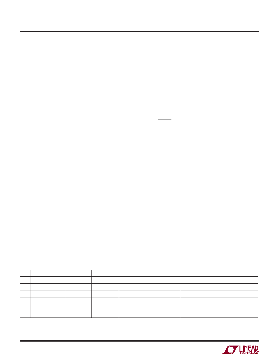
Table 10. Recommended Components Values for 12V Input Supply Li-Ion Battery Backup System Manager
Cell
MAX (ICHG, ICAL) (A) RSNS(BAT)(mΩ)RSNS(FET)(mΩ)
TRANSFORMER INDUCTANCE (μH)
TRANSFORMER VENDOR AND PART NUMBER
3
1
100
50
24
BH 510-1019 TDK PCA14.5/6ER-U03S002
3
2
50
25
12
COILTRONICS VP4-0140-R
3
33
15
9
TDK PCA20EFD-U04S002
4
1
100
50
24
COILTRONICS VPH4-0140-R
4
2
50
25
12
COILTRONICS VPH4-0075-R
4
3
33
15
9
COILTRONICS VP5-0155-R
Note: 1:1 turns ratio for all the transformers listed in the table..
that the power dissipated is never allowed to rise above
the manufacturer’s recommended maximum level.
Switching transition time is another consideration. When
the LTC4110 senses a need to switch any PowerPath
MOSFETs on or off time delays are encountered. MOSFETs
with higher QGATE will require more bulk capacitance on
DCOUT to hold up all the system’s power supply function
during the transition. The transition time of a MOSFET to
an on or off state is directly proportional to the MOSFET
gate charge. Switching times are given in the Electrical
Characteristics Table (see tdDON, tdDOFF).
TRANSFORMER
There are two ways to design a transformer.
1. Design it yourself.
2. Work with a transformer vendor to identify an off-
the-shelf transformer.
Even if you choose to design it yourself, you still have to
nd a transformer manufacturer to make it for you.
We recommend contacting a transformer manufacturer
directly since they often have online tools that can help
you quickly nd and select the right transformer. There are
many off the shelf transformers that can be successfully be
used with the LTC4110. Table 10 shows some suggested
off the shelf transformers.
If you want to design a custom transformer optimized
for your design, Application Note 19 has an example of
how to design a Flyback transformer in the “Transformer”
section.
APPLICATIONS INFORMATION
Regardless of which way you go, we offer the following
thoughts.
Turns ratio affects the duty factor of the power converter
which impacts current and voltage stress on the power
MOSFETs, input and output capacitor RMS currents and
transformer utilization (size vs power). Using a 50%
duty factor under nominal operating conditions usually
gives reasonable results. For a 50% duty factor, the turns
ratio is:
N
V
BAT
DCIN
=
VBAT is the nominal battery voltage. N should be calculated
for the design operating in charging mode and in calibration
mode. The nal turns ratio should be chosen so that it is
approximately equal to the average of the two calculated
values for N. In addition, choose a turns ratio which can
be made from the ratio of small integers. This allows
bilar windings to be used in the transformer, which can
reduce the leakage inductance and the need for aggressive
snubber design, thus improving efciency.
Avoid transformer saturation under all operating conditions
and combinations (usually the biggest problems occur at
high output currents and extreme duty cycles). Choose
the magnetizing inductance so that the current ripple is
about 20% of DC current.
Finally, in low voltage applications, select a transformer
with low winding resistance. This will improve efciency
at heavier loads.
相關(guān)PDF資料 |
PDF描述 |
|---|---|
| LTC4110EUHF | 1-CHANNEL POWER SUPPLY SUPPORT CKT, PQCC38 |
| LTC4151CS-2#TRPBF | 1-CHANNEL POWER SUPPLY SUPPORT CKT, PDSO16 |
| LTC4151HMS#TRPBF | 1-CHANNEL POWER SUPPLY SUPPORT CKT, PDSO10 |
| LTC4151HDD#TRPBF | 1-CHANNEL POWER SUPPLY SUPPORT CKT, PDSO10 |
| LTC4151HDD#PBF | 1-CHANNEL POWER SUPPLY SUPPORT CKT, PDSO10 |
相關(guān)代理商/技術(shù)參數(shù) |
參數(shù)描述 |
|---|---|
| LTC4110EUHF-TRPBF | 制造商:LINER 制造商全稱:Linear Technology 功能描述:Battery Backup System Manager |
| LTC4120IUD#PBF | 制造商:Linear Technology 功能描述:BATTERY CHARGER, 400MA, QFN-16, Battery Type:Li-Ion, Li-Polymer, Input Voltage:4 |
| LTC4150 | 制造商:LINER 制造商全稱:Linear Technology 功能描述:High Voltage, High-Side Current Sense |
| LTC4150_1 | 制造商:LINER 制造商全稱:Linear Technology 功能描述:Coulomb Counter/ Battery Gas Gauge |
| LTC4150CMS | 功能描述:IC COUNTER/GAUGE GAS/BATT 10MSOP RoHS:否 類別:集成電路 (IC) >> PMIC - 電池管理 系列:- 標(biāo)準(zhǔn)包裝:61 系列:- 功能:電源管理 電池化學(xué):鋰離子(Li-Ion)、鋰聚合物(Li-Pol) 電源電壓:4.35 V ~ 5.5 V 工作溫度:-40°C ~ 85°C 安裝類型:表面貼裝 封裝/外殼:22-WFDFN 裸露焊盤 供應(yīng)商設(shè)備封裝:22-DFN(6x3)裸露焊盤 包裝:管件 |
發(fā)布緊急采購,3分鐘左右您將得到回復(fù)。