- 您現(xiàn)在的位置:買賣IC網(wǎng) > PDF目錄370377 > GS-C200 (意法半導(dǎo)體) INTELLIGENT STEPPER MOTOR CONTROLLERS PDF資料下載
參數(shù)資料
| 型號: | GS-C200 |
| 廠商: | 意法半導(dǎo)體 |
| 英文描述: | INTELLIGENT STEPPER MOTOR CONTROLLERS |
| 中文描述: | 智能步進(jìn)電機(jī)控制器 |
| 文件頁數(shù): | 8/31頁 |
| 文件大?。?/td> | 314K |
| 代理商: | GS-C200 |
第1頁第2頁第3頁第4頁第5頁第6頁第7頁當(dāng)前第8頁第9頁第10頁第11頁第12頁第13頁第14頁第15頁第16頁第17頁第18頁第19頁第20頁第21頁第22頁第23頁第24頁第25頁第26頁第27頁第28頁第29頁第30頁第31頁
8/31
GS-C200 AND GS-C200SDESCRIPTION
The increasing popularity of microprocessors and
their very low cost, have contributed to afast growth
of stepper motors usage in a large numbers of
application previously covered by more complex,
bulk and expensive DC motors servo loops. The
GS-C200 and the GS-C200S modules have been
conceived to help theindustrial designer in design-
ing the stepper motor applications based on micro-
processor control.
These modules are programmable intelligent step-
per motor controllers that coordinate highly com-
plex movements and sequential operations. This
capability is performed through the integration of
sophisticated hardware and an easy to learn and
very functional and powerful programming lan-
guage.
Thanks to this high level programming language,
the power of the instruction set and the ability to
condition and control the program execution
through theUSERinputsandoutputs,the GS-C200
and GS-C200S drastically reduce the design time
and start-up manufacturing phase of very complex
systems. The GS-C200S offers an advanced and
powerful instruction set that includes also the con-
ditional jump which allows for more efficient pro-
gram-ming. TheGS-C200,the GS-C200S and their
companion modules, the GS-D200 and the GS-
D200S, can be used to drive in chopped mode of
bipolar stepper motor with a 2/2.5A maximum
phase current rating.
The two modules (GS-C and GS-D) are available
also on a single Eurocard board named respec-
tively GS-DC200, GS-DC200S and GS-DC200SS
according to the various modules combination (see
the relevant data sheet). In the following the mod-
ules will be generically named GS-C. The specific
module part number will be used when the feature
is unique to thatmodule.
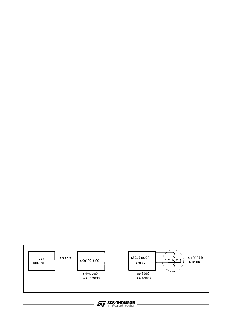
A MOTION SYSTEM ARCHITECTURE
A complete motion system controlled by a host
computer is normally configured as per fig. 3.
Figure 3. A Motion System BlockDiagram
The GS-C logical and functional architecture is
shown in fig. 1 and it includes the following basic
blocks:
– Interface to the Host Computer via an RS232
communication port.
– Address and baudrate selection.
– Interface to the Sequencer-Driver (in particular
but not exclusively, to the GS-D200 or GS-
D200S)via 5 output and 3 input lines
– Command Interpreter and Executor.
– Program storage area
– Power Supply.
The above mentioned functions are performed by
the GS-Cwithout the addition of anyexternal com-
ponent, and the module flexibility is further en-
hanced by the use of only one unregulated supply
voltage that can be the same used to supply the
Sequencer-Driver (from 12V up to 40V).
Commands are sentto the module by a Host Com-
puter or by a simple video terminal during the
programming/debugging phase through an RS232
serial port. They are interpreted and validated by
the command interpreter and executed through the
Sequencer-Driver interface.
Command execution can be conditioned and con-
trolled by the status of the USER IN-OUTinterface.
Aprogram storage area has been added to perma-
nently store a program in an on-board EEPROM;
this is particulary beneficial to obtain a low cost
stand-alone controller that doesnot need any con-
nection to an external computer or to store pro-
grams frequently used in complex motion
sequencies thus reducing the host computer bur-
den and speeding up the systemprocessing.
Particular attention has been given to the simplicity
of the instruction setto allowan easy design of the
system to those designers that are notvery familiar
with microprocessor software and programming.
In thefollowing a detailed description of the various
functional blocks is given.
GS-C200/ GS-C200S
相關(guān)PDF資料 |
PDF描述 |
|---|---|
| GS-D200M | Industrial Control IC |
| GS-D200 | 2/2.5A Bipolar Stepper Motor Driver Modules(2/2.5A雙極型步進(jìn)電機(jī)驅(qū)動器模塊) |
| GS-D200S | 2/2.5A Bipolar Stepper Motor Driver Modules(2/2.5A雙極型步進(jìn)電機(jī)驅(qū)動器模塊) |
| GS-D500A | 100V/5A STEP AND MICROSTEP DRIVE BOARD FOR STEPPER MOTORS |
| GS-DC200 | STEPPER MOTOR CONTROL AND DRIVE SYSTEM FAMILY |
相關(guān)代理商/技術(shù)參數(shù) |
參數(shù)描述 |
|---|---|
| GS-C200S | 制造商:STMICROELECTRONICS 制造商全稱:STMicroelectronics 功能描述:INTELLIGENT STEPPER MOTOR CONTROLLERS |
| GSC20-12 | 功能描述:線性和開關(guān)式電源 20W 12V @ 1.7A RoHS:否 制造商:TDK-Lambda 產(chǎn)品:Switching Supplies 開放式框架/封閉式:Enclosed 輸出功率額定值:800 W 輸入電壓:85 VAC to 265 VAC 輸出端數(shù)量:1 輸出電壓(通道 1):20 V 輸出電流(通道 1):40 A 商用/醫(yī)用: 輸出電壓(通道 2): 輸出電流(通道 2): 安裝風(fēng)格:Rack 長度: 寬度: 高度: |
| GSC20-12G | 功能描述:線性和開關(guān)式電源 20W 12V @ 1.7A RoHS:否 制造商:TDK-Lambda 產(chǎn)品:Switching Supplies 開放式框架/封閉式:Enclosed 輸出功率額定值:800 W 輸入電壓:85 VAC to 265 VAC 輸出端數(shù)量:1 輸出電壓(通道 1):20 V 輸出電流(通道 1):40 A 商用/醫(yī)用: 輸出電壓(通道 2): 輸出電流(通道 2): 安裝風(fēng)格:Rack 長度: 寬度: 高度: |
| GSC20-15 | 功能描述:線性和開關(guān)式電源 20W 15V @ 1.4A RoHS:否 制造商:TDK-Lambda 產(chǎn)品:Switching Supplies 開放式框架/封閉式:Enclosed 輸出功率額定值:800 W 輸入電壓:85 VAC to 265 VAC 輸出端數(shù)量:1 輸出電壓(通道 1):20 V 輸出電流(通道 1):40 A 商用/醫(yī)用: 輸出電壓(通道 2): 輸出電流(通道 2): 安裝風(fēng)格:Rack 長度: 寬度: 高度: |
| GSC20-15G | 功能描述:線性和開關(guān)式電源 20W 15V @ 1.4A RoHS:否 制造商:TDK-Lambda 產(chǎn)品:Switching Supplies 開放式框架/封閉式:Enclosed 輸出功率額定值:800 W 輸入電壓:85 VAC to 265 VAC 輸出端數(shù)量:1 輸出電壓(通道 1):20 V 輸出電流(通道 1):40 A 商用/醫(yī)用: 輸出電壓(通道 2): 輸出電流(通道 2): 安裝風(fēng)格:Rack 長度: 寬度: 高度: |
發(fā)布緊急采購,3分鐘左右您將得到回復(fù)。