- 您現(xiàn)在的位置:買賣IC網(wǎng) > PDF目錄298890 > BU-65170G1-290 (DATA DEVICE CORP) 2 CHANNEL(S), 1M bps, MIL-STD-1553 CONTROLLER, CDSO70 PDF資料下載
參數(shù)資料
| 型號: | BU-65170G1-290 |
| 廠商: | DATA DEVICE CORP |
| 元件分類: | 微控制器/微處理器 |
| 英文描述: | 2 CHANNEL(S), 1M bps, MIL-STD-1553 CONTROLLER, CDSO70 |
| 封裝: | CERAMIC PACKAGE-70 |
| 文件頁數(shù): | 14/47頁 |
| 文件大小: | 1143K |
| 代理商: | BU-65170G1-290 |
第1頁第2頁第3頁第4頁第5頁第6頁第7頁第8頁第9頁第10頁第11頁第12頁第13頁當前第14頁第15頁第16頁第17頁第18頁第19頁第20頁第21頁第22頁第23頁第24頁第25頁第26頁第27頁第28頁第29頁第30頁第31頁第32頁第33頁第34頁第35頁第36頁第37頁第38頁第39頁第40頁第41頁第42頁第43頁第44頁第45頁第46頁第47頁
21
Data Device Corporation
www.ddc-web.com
BU-65170/61580/61585
T-6/09-0
Monitor Command Stack Pointer B (fixed location)
Monitor Data Stack A
0800-0FFF
Monitor Command Stack A
0400-07FF
Not Used
0300-03FF
Selective Monitor Lookup Table (fixed area)
0280-02FF
Not Used
0108-027F
Monitor Data Stack Pointer B (fixed location)
0107
Not Used
0104-0105
Monitor Data Stack Pointer A (fixed location)
0103
Monitor Command Stack Pointer A (fixed location)
0102
Not Used
0000-0101
DESCRIPTION
0106
TABLE 30. TYPICAL SELECTIVE MESSAGE MONITOR
MEMORY MAP (SHOWN FOR 4K RAM)
ADDRESS
(HEX)
PROCESSOR AND MEMORY INTERFACE
The ACE terminals provide much flexibility for interfacing to a
host processor and optional external memory. FIGURE 1 shows
that there are 14 control signals, 6 of which are dual purpose, for
the processor/memory interface. FIGURES 9 through 14 illus-
trate six of the configurations that may be used for interfacing a
BU-65170 or BU-61580 to a host processor bus. The various
possible configurations serve to reduce to an absolute minimum
the amount of glue logic required to interface to 8-, 16-, and
32-bit processor buses. Also included are features to facilitate
interfacing to processors that do not have a “wait state” type of
handshake acknowledgement. Finally, the ACE supports a reli-
able interface to an external dual port RAM. This type of interface
minimizes the portion of the available processor bandwidth
required to access the 1553 RAM.
The 16-bit buffered mode (FIGURE 9) is the most common con-
figuration used. It provides a direct, shared RAM interface to a
16-bit or 32-bit microprocessor. In this mode, the ACE's internal
address and data buffers provide the necessary isolation
between the host processor's address and data buses and the
corresponding internal memory buses. In the buffered mode, the
1553 shared RAM address space limit is the BU-65170/61580's
4K words of internal RAM. The 16-bit buffered mode provides a
pair of pin-programmable options:
15
13
0
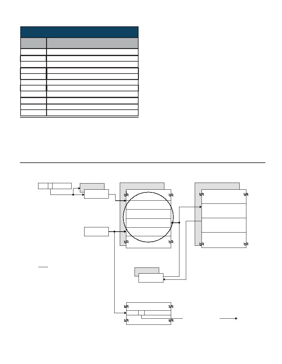
BLOCK STATUS WORD
TIME TAG WORD
DATA BLOCK POINTER
RECEIVED COMMAND
WORD
CONFIGURATION
REGISTER #1
MONITOR COMMAND
STACK POINTERS
MONITOR
COMMAND STACKS
CURRENT
AREA B/A
MONITOR DATA
STACKS
MONITOR DATA
BLOCK #N + 1
MONITOR DATA
BLOCK #N
CURRENT
COMMAND WORD
MONITOR DATA
STACK POINTERS
IF THIS BIT IS "0" (NOT SELECTED)
NO WORDS ARE STORED IN EITHER
THE COMMAND STACK OR DATA STACK.
IN ADDITION, THE COMMAND AND DATA
STACK POINTERS WILL NOT BE UPDATED.
NOTE
SELECTIVE MONITOR
LOOKUP TABLES
SELECTIVE MONITOR
ENABLE
(SEE NOTE)
OFFSET BASED ON
RTA4-RTA0, T/R, SA4
FIGURE 8. SELECTIVE MESSAGE MONITOR MEMORY MANAGEMENT
相關PDF資料 |
PDF描述 |
|---|---|
| BU-65565F4-300N | 4 CHANNEL(S), 1M bps, MIL-STD-1553 CONTROLLER, XMA |
| BU-65565B3-900 | 3 CHANNEL(S), 1M bps, MIL-STD-1553 CONTROLLER, XMA |
| BU-65565F4-900 | 4 CHANNEL(S), 1M bps, MIL-STD-1553 CONTROLLER, XMA |
| BU-65565C2-300 | 2 CHANNEL(S), 1M bps, MIL-STD-1553 CONTROLLER, XMA |
| BU-65565B1-300N | 1 CHANNEL(S), 1M bps, MIL-STD-1553 CONTROLLER, XMA |
相關代理商/技術參數(shù) |
參數(shù)描述 |
|---|---|
| BU65170G5-100 | 制造商:未知廠家 制造商全稱:未知廠家 功能描述:Interface IC |
| BU65170G5-110 | 制造商:未知廠家 制造商全稱:未知廠家 功能描述:Interface IC |
| BU65170G5-120 | 制造商:未知廠家 制造商全稱:未知廠家 功能描述:Interface IC |
| BU65170G5-200 | 制造商:未知廠家 制造商全稱:未知廠家 功能描述:Interface IC |
| BU65170G5-300 | 制造商:未知廠家 制造商全稱:未知廠家 功能描述:Interface IC |
發(fā)布緊急采購,3分鐘左右您將得到回復。