- 您現(xiàn)在的位置:買賣IC網(wǎng) > PDF目錄294783 > A14100A-STDCQG256B FPGA, 1377 CLBS, 30000 GATES, 85 MHz, CQFP256 PDF資料下載
參數(shù)資料
| 型號: | A14100A-STDCQG256B |
| 元件分類: | FPGA |
| 英文描述: | FPGA, 1377 CLBS, 30000 GATES, 85 MHz, CQFP256 |
| 封裝: | CERAMIC, QFP-256 |
| 文件頁數(shù): | 54/54頁 |
| 文件大?。?/td> | 343K |
| 代理商: | A14100A-STDCQG256B |
第1頁第2頁第3頁第4頁第5頁第6頁第7頁第8頁第9頁第10頁第11頁第12頁第13頁第14頁第15頁第16頁第17頁第18頁第19頁第20頁第21頁第22頁第23頁第24頁第25頁第26頁第27頁第28頁第29頁第30頁第31頁第32頁第33頁第34頁第35頁第36頁第37頁第38頁第39頁第40頁第41頁第42頁第43頁第44頁第45頁第46頁第47頁第48頁第49頁第50頁第51頁第52頁第53頁當(dāng)前第54頁

RadTolerant FPGAs
v3.1
1-5
output track is dedicated to the output of a particular
module. Long segments are uncommitted and can be
assigned during routing. Each output segment spans
four channels (two above and two below), except near
the top and bottom of the array where edge effects
occur. Long vertical tracks contain either one or two
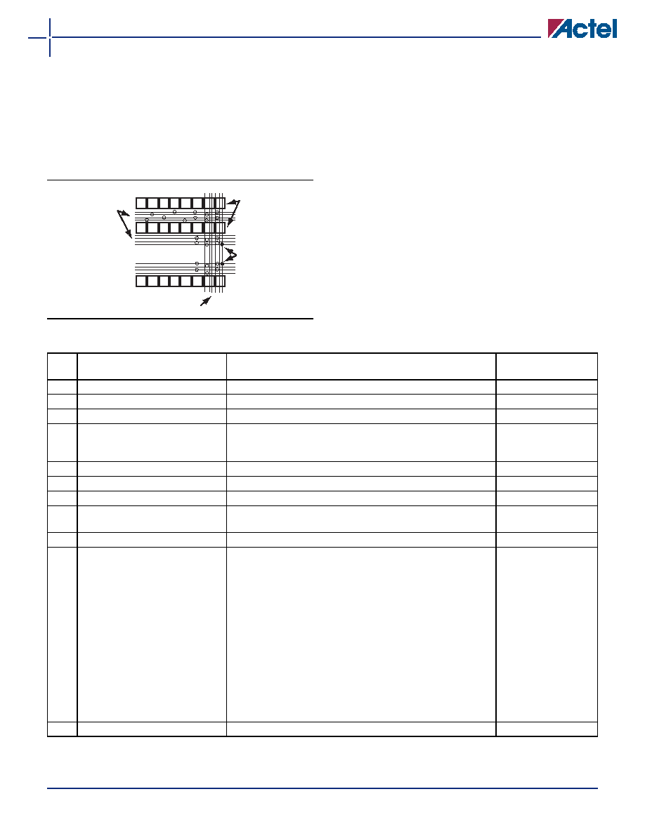
segments. An example of vertical routing tracks and
segments is shown in Figure 1-5.
Antifuse Structures
An antifuse is a "normally open" structure as opposed to
the normally closed fuse structure used in PROMs
(programmable read-only memory) or PALs (programmed
array logic). The use of antifuses to implement a PLD
(programmable logic device) results in highly testable
structures, as well as efficient programming algorithms.
The structure is highly testable because there are no pre-
existing connections, enabling temporary connections to
be
made
using
pass
transistors.
These
temporary
connections can isolate individual antifuses to be
programmed, and also isolate individual circuit structures
to be tested. This can be done both before and after
programming. For example, all metal tracks can be tested
for continuity and shorts between adjacent tracks, and
the functionality of all logic modules can be verified.
Figure 1-5 Routing Structure
Vertical Routing Tracks
Segmented
Horizontal
Routing
Tracks
Logic
Modules
Antifuses
Table 1-1 Actel MIL-STD-883 Product Flow
Step
Screen
883 Method
883 - Class B
Requirement
1.
Internal Visual
2010, Test Condition B
100%
2.
Temperature Cycling
1010, Test Condition C
100%
3.
Constant Acceleration
2001, Test Condition D or E, Y1, Orientation Only
100%
4.
Seal
a. Fine
b. Gross
1014
100%
5.
Visual Inspection
2009
100%
6.
Pre-Burn-In Electrical Parameters
In accordance with applicable Actel device specification
100%
7.
Burn-in Test
1015, Condition D, 160 hours @ 125°C or 80 hours @ 150°C
100%
8.
Interim (Post-Burn-In) Electrical
Parameters
In accordance with applicable Actel device specification
100%
9.
Percent Defective Allowable
5%
All Lots
10.
Final Electrical Test
a. Static Tests
(1) 25°C (Subgroup 1, Table I)
(2) –55°C and +125°C
(Subgroups 2, 3, Table I)
b. Functional Tests
(1) 25°C (Subgroup 7, Table I)
(2) –55°C and +125°C
(Subgroups 8A and 8B, Table I)
c. Switching Tests at 25°C
(Subgroup 9, Table I)
In accordance with applicable Actel device specification, which
includes a, b, and c:
5005
100%
11.
External Visual
2009
100%
Note: When Destructive Physical Analysis (DPA) is performed on Class B devices, the step coverage requirement as specified in Method
2018 must be waived.
相關(guān)PDF資料 |
PDF描述 |
|---|---|
| A14100A-STDCQG256M | FPGA, 1377 CLBS, 30000 GATES, 85 MHz, CQFP256 |
| A1460A-1PQ160M | FPGA, 848 CLBS, 6000 GATES, 125 MHz, PQFP160 |
| A1460A-PQ160M | FPGA, 848 CLBS, 6000 GATES, 100 MHz, PQFP160 |
| A1460A-1TQ176M | FPGA, 848 CLBS, 6000 GATES, 125 MHz, PQFP176 |
| A1460A-TQ176M | FPGA, 848 CLBS, 6000 GATES, 100 MHz, PQFP176 |
相關(guān)代理商/技術(shù)參數(shù) |
參數(shù)描述 |
|---|---|
| A14100ASTDPQ257B | 制造商:未知廠家 制造商全稱:未知廠家 功能描述:ASIC |
| A14100ASTDPQ257C | 制造商:未知廠家 制造商全稱:未知廠家 功能描述:ASIC |
| A14100ASTDPQ257M | 制造商:未知廠家 制造商全稱:未知廠家 功能描述:ASIC |
| A14100B-1BG313C | 制造商:未知廠家 制造商全稱:未知廠家 功能描述:Field Programmable Gate Array (FPGA) |
| A14100B-2BG313C | 制造商:未知廠家 制造商全稱:未知廠家 功能描述:Field Programmable Gate Array (FPGA) |
發(fā)布緊急采購,3分鐘左右您將得到回復(fù)。