- 您現(xiàn)在的位置:買賣IC網(wǎng) > PDF目錄359432 > VSC870 (VITESSE SEMICONDUCTOR CORP) High Performance Serial Backplane Transceiver PDF資料下載
參數(shù)資料
| 型號: | VSC870 |
| 廠商: | VITESSE SEMICONDUCTOR CORP |
| 元件分類: | 通用總線功能 |
| 英文描述: | High Performance Serial Backplane Transceiver |
| 中文描述: | LINE TRANSCEIVER, PBGA192 |
| 封裝: | BGA-192 |
| 文件頁數(shù): | 24/40頁 |
| 文件大?。?/td> | 511K |
| 代理商: | VSC870 |
第1頁第2頁第3頁第4頁第5頁第6頁第7頁第8頁第9頁第10頁第11頁第12頁第13頁第14頁第15頁第16頁第17頁第18頁第19頁第20頁第21頁第22頁第23頁當前第24頁第25頁第26頁第27頁第28頁第29頁第30頁第31頁第32頁第33頁第34頁第35頁第36頁第37頁第38頁第39頁第40頁
VITESSE
Data Sheet
VSC870
High Performance Serial
Backplane Transceiver
Page 24
G52190-0, Rev 4.1
01/05/01
VITESSE
SEMICONDUCTOR CORPORATION
741 Calle Plano
Camarillo, CA 93012
Tel: (800) VITESSE
FAX: (805) 987-5896
Email: prodinfo@vitesse.com
Internet: www.vitesse.com
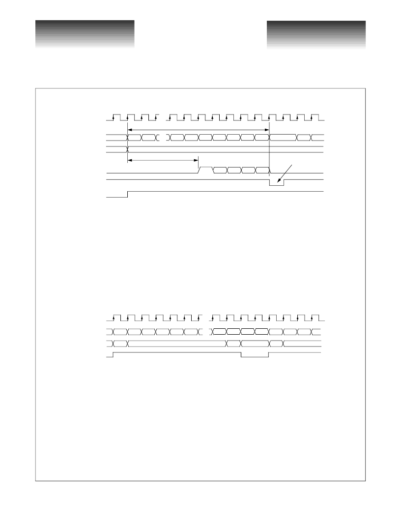
Figure 8: Multi Queue Transmitter Functional Timing (with early arbitration)
2.4 Receiver Operation
In Packet Mode, the receiver examines incoming words and generates the data type signals accordingly. Refer to
section 2.2
“
Data Encoding Format
”
for the coding of these signals. If the receive word is an IDLE word, the RXWA
signal is set LOW so the FIFO can use this signal to filter out these null data words. If the receiver detects an ACK for
the connection request on the transmit side, the ACK/RCLK signal is asserted for one word clock. The RXOUT data
bus and RXTYP outputs can be tristated by asserting RXEN. CRQ words, header words, IDLE words and data words
are sent to the receiving port card. A functional timing diagram for a typical receiver operation is shown in the
following figure. See Application Note 31 for more detailed information.
Figure 9: Receive Channel Functional Timing
2.5 Flow Control Channel
The transceiver can support a back pressure mechanism by providing a flow control channel. This channel
supports two logic states that are sent from the receiving port card back to the transmitting port card. The flow
control channel is time shared with the signaling between the switch chip and the transceiver for acknowledgment
and response bits for Multi Queue connection requests. Therefore, it can only guarantee to pass the state information
from the RTR pin at the receiving port card through the switch and to the REN pin at the transmitting port card. The
REN pin is also shared between the flow control channel and the transceiver
’
s connection request retransmission
logic. To apply backpressure to the transmitting port card, the RTR signal should be set LOW. An application for this
flow control channel is to prevent the FIFO on the receiving side from overflowing. In this case, the
WCLK
TXIN[31:0]
TXTYP[1:0]
REN
CRQ
D0
D1
D2
3
1
Last 13 words of current data packet
RTM/TCLK
Time to select data queue
and reconfigure switch
Minimum of 9 clock cycles
DX
DX
DX
DX
DX
DX
DX
DX
HDR
ACK/RCLK
P0
P1
P2
P3
WCLK
RXIN[31:0]
RXTYP[1:0]
RXWA
HDR
D0
D1
D2
D3
D4
DN
2
1
HDR
D0
D1
CRQ
idle
idle
3
1
0
2
相關(guān)PDF資料 |
PDF描述 |
|---|---|
| VSC870TX | High Performance Serial Backplane Transceiver |
| VSC872 | 80 Gb/s Intelligent Switch Fabric |
| VSC874 | 10 Gbps Queue Manager with Integrated SPI4.2 Interface |
| VSC880 | High Performance 16x16 Serial Crosspoint Switch |
| VSC9110 | Target Specification |
相關(guān)代理商/技術(shù)參數(shù) |
參數(shù)描述 |
|---|---|
| VSC870TX | 制造商:VITESSE 制造商全稱:Vitesse Semiconductor Corporation 功能描述:High Performance Serial Backplane Transceiver |
| VSC872 | 制造商:VITESSE 制造商全稱:Vitesse Semiconductor Corporation 功能描述:80 Gb/s Intelligent Switch Fabric |
| VSC872TV01 | 制造商:Vitesse Semiconductor Corporation 功能描述: |
| VSC874 | 制造商:VITESSE 制造商全稱:Vitesse Semiconductor Corporation 功能描述:10 Gbps Queue Manager with Integrated SPI4.2 Interface |
| VSC880 | 制造商:VITESSE 制造商全稱:Vitesse Semiconductor Corporation 功能描述:High Performance 16x16 Serial Crosspoint Switch |
發(fā)布緊急采購,3分鐘左右您將得到回復(fù)。