- 您現(xiàn)在的位置:買賣IC網(wǎng) > PDF目錄384047 > UPD98409GN-LMU (NEC Corp.) ATM LIGHT SAR CONTROLLER PDF資料下載
參數(shù)資料
| 型號: | UPD98409GN-LMU |
| 廠商: | NEC Corp. |
| 英文描述: | ATM LIGHT SAR CONTROLLER |
| 中文描述: | 自動柜員機燈特區(qū)控制器 |
| 文件頁數(shù): | 6/36頁 |
| 文件大小: | 402K |
| 代理商: | UPD98409GN-LMU |
第1頁第2頁第3頁第4頁第5頁當前第6頁第7頁第8頁第9頁第10頁第11頁第12頁第13頁第14頁第15頁第16頁第17頁第18頁第19頁第20頁第21頁第22頁第23頁第24頁第25頁第26頁第27頁第28頁第29頁第30頁第31頁第32頁第33頁第34頁第35頁第36頁
6
μ
PD98409
1. PIN FUNCTION
The pin function of the
μ
PD98409 is descibed below. A detailed explanation of how to use each pin, and the
points to be noted in using the pins are given in
μ
PD98409 User’s Manual (Document Number: S12776E). Be sure
to refer to this user’s manual.
The following describes the I/O levels in the tables.
LV-TTL input : Can be connected to 5 V CMOS output
TTL output
: Can be connected to 5 V TTL input, V
OH
= 3.3 V, I
OL
= 6 mA
CMOS output : 3.3 V CMOS output, V
OH
= 3.3 V, I
OL
= 12 mA
PCI input
: 5/3.3 V PCI input
PCI output
: 5/3.3 V PCI output
1.1 PHY Device Interface Pin
PHY device interfaces include a UTOPIA interface through which the
μ
PD98409 transfers ATM cells with a PHY
device, and a PHY control interface by which the
μ
PD98409 controls the PHY device.
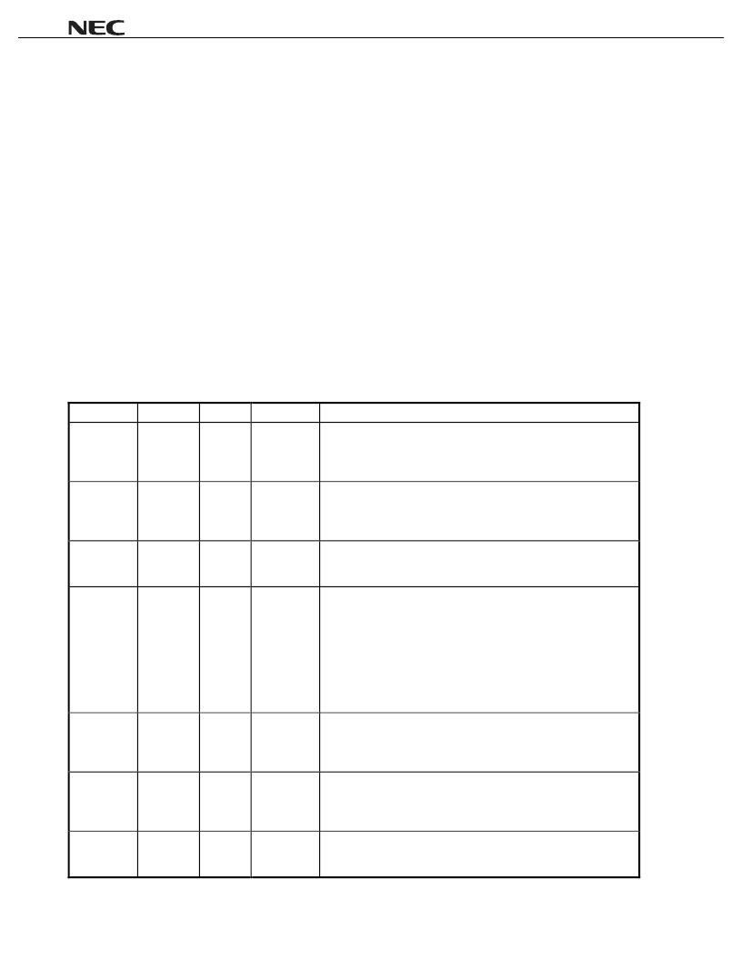
1.1.1 UTOPIA interface
(1/2)
Pin Name
Pin No.
I/O
I/O Level
Function
Rx7-Rx0
116 - 119,
123 - 126
I
LV-TTL
Receive Data Bus.
Rx7 through Rx0 constitute an 8-bit input bus which inputs data
received from a network in byte format from a PHY device. The
μ
PD98409 loads data in at the rising edge of RCLK.
RSOC
133
I
LV-TTL
Receive Start Cell.
The RSOC signal is input in synchronization with the first byte of the
cell data from a PHY device. This signal remains high while the first
byte of the header is input to Rx7 through Rx0.
RENBL_B
132
O
TTL
Receive Enable.
The RENBL_B signal indicates to a PHY device that the
μ
PD98409 is
ready to receive data in the next clock cycle.
EMPTY_B/
RxCLAV
131
I
LV-TTL
PHY Output Buffer Empty/Rx Cell Available.
This signal notifies the
μ
PD98409 that there is no cell data to be
transferred in the receive FIFO and that no receive data can be
supplied to the PHY device. When the UTOPIA interface is in the
octet-level handshake mode, this signal serves as EMPTY_B,
indicating that the data on Rx7 through Rx0 are invalid in the current
clock cycle. In the cell-level handshake mode, it serves as RxCLAV,
indicating that there is no cell to be supplied next after the transfer of
the current cell is completed.
RCLK
128
O
TTL
Receive Clock.
This is a synchronization clock used to transfer cell data with the PHY
device at the receive side. The system clock input to the BUSCLK pin
is output from this pin as is.
Tx7-Tx0
141 - 144,
146 - 149
O
TTL
Transmit Data Bus.
Tx7 through Tx0 constitute an 8-bit output bus which outputs transmit
data in byte format to a PHY device. The
μ
PD98409 outputs data at
the rising edge of TCLK.
TSOC
135
O
TTL
Transmit Start of Cell.
The TSOC signal is output in synchronization with the first byte of
transmit cell data.
相關(guān)PDF資料 |
PDF描述 |
|---|---|
| UPD98409 | ATM LIGHT SAR CONTROLLER |
| UPG158TB-E3 | L, S- BAND SPDT SWITCH |
| UPG158 | L, S- BAND SPDT SWITCH |
| UPG158TB | L, S- BAND SPDT SWITCH |
| UPG2009TB | NECs L, S-BAND 4W SPDT SWITCH |
相關(guān)代理商/技術(shù)參數(shù) |
參數(shù)描述 |
|---|---|
| UPD98411 | 制造商:NEC 制造商全稱:NEC 功能描述:ATM QUAD SONET FRAMER |
| UPD98411GN-MMU | 制造商:NEC 制造商全稱:NEC 功能描述:ATM QUAD SONET FRAMER |
| UPD98412 | 制造商:未知廠家 制造商全稱:未知廠家 功能描述:Telecommunication IC |
| UPD98412N7-H6 | 制造商:未知廠家 制造商全稱:未知廠家 功能描述:ATM DATA-LINK SWITCHING/ROUTING|CMOS|BGA|576PIN|PLASTIC |
| UPD98414 | 制造商:未知廠家 制造商全稱:未知廠家 功能描述:Telecommunication IC |
發(fā)布緊急采購,3分鐘左右您將得到回復。