- 您現(xiàn)在的位置:買賣IC網(wǎng) > PDF目錄383967 > TUA6100B6 (INFINEON TECHNOLOGIES AG) Components for Satellite Receiver Units PDF資料下載
參數(shù)資料
| 型號: | TUA6100B6 |
| 廠商: | INFINEON TECHNOLOGIES AG |
| 英文描述: | Components for Satellite Receiver Units |
| 中文描述: | 元件衛(wèi)星接收單元 |
| 文件頁數(shù): | 12/46頁 |
| 文件大?。?/td> | 819K |
| 代理商: | TUA6100B6 |
第1頁第2頁第3頁第4頁第5頁第6頁第7頁第8頁第9頁第10頁第11頁當前第12頁第13頁第14頁第15頁第16頁第17頁第18頁第19頁第20頁第21頁第22頁第23頁第24頁第25頁第26頁第27頁第28頁第29頁第30頁第31頁第32頁第33頁第34頁第35頁第36頁第37頁第38頁第39頁第40頁第41頁第42頁第43頁第44頁第45頁第46頁
Preliminary Specification
TUA6100B6
High-Frequency-Products
7
26.1.01
8.11 GHz PLL
Normally in DCR systems it is necessary that the synthesizer VCO oscillates exact at the desired
receiving frequency.
The following description shows a new patent pending double PLL tuning system without this
requirement and enables some features that other concepts do not have.
The main benefit of this new concept is :
– the accurate 0 / 90° generation of the LO signals for the RF input mixer,
– no oscillator on input frequency,
– a programmed frequency offset of synthesizer VCO to the RF input frequency and due to that a
– very low VCO oscillator pulling and self mixing according to power crosstalk of RF input and
– the possibility of splitting the tuning range into bands.
Responsible for these advantages is a 2
nd
GHz PLL system with two VCO’s at 4 x Fin.
This 2
nd
GHz PLL system is located in the broken up feedback of the synthesizer PLL 1 between the
VCO1 and the programmable counter input N1. This represents a system of two cascaded PLL’s.
This location enables a shift of the synthesizer VCO1 to other frequencies, independent of the
required input LO frequency of the RF mixers.
In this case the synthesizer VCO must
not
oscillate at the required LO frequency of the mixer input.
Nevertheless the synthesizer PLL is referenced to the LO frequency of the mixer input which makes it
easy to program the PLL because it is set exact to the receiving frequency.
Another benefit is the exact mapping of the PLL stepsize to the tuning frequency.
This is not possible in a conventional PLL tuning system with the feedback of the VCO1 direct to the
programmable counters N1, if the VCO1 is not running on the RF input frequency.
This may become clear in the above concept, if the interrupted PLL 1 is closed and the LO I/Q
output is cut off from node x.
In this case step size and tuning frequency have additional terms of calculation. Depending on the
system concept. they do not fit to the programmed values of the synthesizer PLL 1, because it is
referenced to the VCO1 and no longer to the LO I/Q output.
( following dependencies will become valid, F
tune
= (N2 / R2) F
vco1
and F
step
= (N2 / R2) PLL1
step
).
The R2 and N2 counters of the GHz PLL enable a programmable frequency offset of the synthesizer
VCO to the RF input as well as a splitting of the required RF tuning range.
For the band splitting feature the counters R2 and N2 of the GHz PLL must be used with 2 different
values (e.g. 4/2 and 4/3). As a result VCO1 will pass his range twice, while the LO I/Q output to mixer
will have a tuning range which is split into 2 bands.
In the feedback of the GHz PLL is located the high speed Johnson-counter
prescaler for the two 3.4 - 8.6 GHz VCO’s and accurate 0 / 90° LO generator.
(Q2) which acts as
The complete GHz PLL is designed in high speed ECL cascoded technology which enables counter
frequencies up to 15 GHz , oscillator frequencies up to 10 GHz and phase detector / charge pump
signal slopes of less then 100 ps.
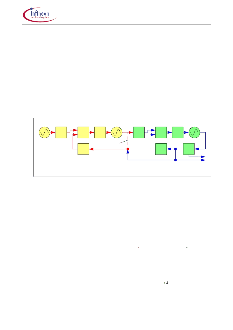
cascaded PLL system
Fref
R2
R1
PD1
CP1
N1
PD2
CP2
N2
interrupted
PLL 1
LO I/Q output
to mixer
R : reference counter
PD : phase detector
CP : charge pump
VCO : voltage controlled oscillator
Q2 : Quadraturphase + prescaler
N : main counter
Q2
PLL 2
VCO2
VCO1
PLL 1 (Synthesizer)
X
相關(guān)PDF資料 |
PDF描述 |
|---|---|
| TV06B5V0K-G | SMD TRANSLENT VOLTAGE SUPPRESSOR |
| TV06B6V0J-G | SMD TRANSLENT VOLTAGE SUPPRESSOR |
| TV06B6V0K-G | SMD TRANSLENT VOLTAGE SUPPRESSOR |
| TV06B7V0J-G | SMD TRANSLENT VOLTAGE SUPPRESSOR |
| TV06B7V0K-G | SMD TRANSLENT VOLTAGE SUPPRESSOR |
相關(guān)代理商/技術(shù)參數(shù) |
參數(shù)描述 |
|---|---|
| TUA6110XS | 制造商:未知廠家 制造商全稱:未知廠家 功能描述:RF Mixer |
| TUA6120 | 制造商:INFINEON 制造商全稱:Infineon Technologies AG 功能描述:Gain controlled I/Q Mixer for Digital QPSK or 8PSK Sat Signals |
| TUA9001XT | 制造商:Infineon Technologies AG 功能描述:Tuners 38.4MHz 65-Pin WFSGA |
| TUB-1.25(100pcs) | 制造商:JST Manufacturing 功能描述:_ 3.4mm 0.25 to 1.65mm2 Bulk |
| TUB-120-AKA-010 | 制造商:ATC DIVERSIFIED ELECTRONICS 功能描述:RELAY;TIME DLY RLY INTER.ON OPT RLY OTPT |
發(fā)布緊急采購,3分鐘左右您將得到回復。