- 您現(xiàn)在的位置:買(mǎi)賣(mài)IC網(wǎng) > PDF目錄384031 > TSB14C01AMHV (Texas Instruments, Inc.) Circular Connector; No. of Contacts:79; Series:MS27497; Body Material:Aluminum; Connecting Termination:Crimp; Connector Shell Size:20; Circular Contact Gender:Pin; Circular Shell Style:Wall Mount Receptacle; Insert Arrangement:20-35 RoHS Compliant: No PDF資料下載
參數(shù)資料
| 型號(hào): | TSB14C01AMHV |
| 廠商: | Texas Instruments, Inc. |
| 元件分類: | 圓形連接器 |
| 英文描述: | Circular Connector; No. of Contacts:79; Series:MS27497; Body Material:Aluminum; Connecting Termination:Crimp; Connector Shell Size:20; Circular Contact Gender:Pin; Circular Shell Style:Wall Mount Receptacle; Insert Arrangement:20-35 RoHS Compliant: No |
| 中文描述: | 5V的電機(jī)及電子學(xué)工程師聯(lián)合會(huì)1394-1995背板收發(fā)器/仲裁者 |
| 文件頁(yè)數(shù): | 9/31頁(yè) |
| 文件大?。?/td> | 424K |
| 代理商: | TSB14C01AMHV |
第1頁(yè)第2頁(yè)第3頁(yè)第4頁(yè)第5頁(yè)第6頁(yè)第7頁(yè)第8頁(yè)當(dāng)前第9頁(yè)第10頁(yè)第11頁(yè)第12頁(yè)第13頁(yè)第14頁(yè)第15頁(yè)第16頁(yè)第17頁(yè)第18頁(yè)第19頁(yè)第20頁(yè)第21頁(yè)第22頁(yè)第23頁(yè)第24頁(yè)第25頁(yè)第26頁(yè)第27頁(yè)第28頁(yè)第29頁(yè)第30頁(yè)第31頁(yè)
TSB14C01A, TSB14C01AI, TSB14C01AM
5-V IEEE 1394-1995 BACKPLANE TRANSCEIVER/ARBITER
SGLS107A – FEBRUARY 1999 – REVISED NOVEMBER 1999
9
POST OFFICE BOX 655303
DALLAS, TEXAS 75265
APPLICATION INFORMATION
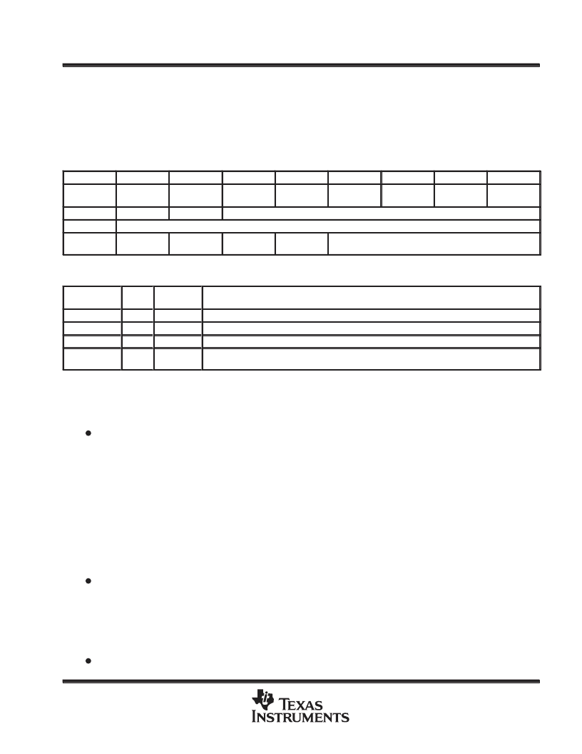
internal register configuration
The accessible internal registers of this device are listed in Table 2. Bit field descriptions for the registers are
given in Table 3.
Table 2. Format for Registers
ADDRESS
0
1
2
3
4
5
6
7
0000
Physical
ID[0]
Physical
ID[1]
Physical
ID[2]
Physical
ID[3]
Physical
ID[4]
Physical
ID[5]
Reserved
Reserved
0001
INHB
IBR
RESERVED
0011
RESERVED
0100
Priority
level[0]
Priority
level[1]
Priority
level[2]
Priority
level[3]
RESERVED
Table 3. Register Bit Field Key
ááááááááááááááááááááááááááááááááá
á
á
áááááááááááááááááááááááááááááááá
transceiver selection
ááá
áááááááááááááááááááááááááááááááá
Physical ID
ááááááááááááááááááááááááááááááááá
IBR
á
(Bits)
á
áá
Read/Write
1
Read/Write
Read/Write
á
áááááááááááááááááááááá
Physical identification. Physical ID is the address of the local node and is set to zero on power up.
Initiate Bus Reset. IBR is turned on by the link and turned off by the phy when reset is complete.
á
6
1
INHB
Read/Write
Inhibit Drivers. INHB is used to turn off the drivers to TDATA and TSTRB.
ááááááááááááááááááááááááááááááááá
ááá
á
á
á
á
áááááááááááááááááááááá
á
The system designer must select transceivers appropriate to the system requirements to be used with the
TSB14C01A and the link layer selected. The following lists requirements for the transceivers needed.
The transceivers used must be appropriate to the backplane technology used.
The various backplane technologies require different electrical characteristics in their backplanes. For
example BTL uses an operating voltage on the backplane of 2.1 V and a characteristic impedance of 33
while GTL uses an operating voltage of 1.2 V and a characteristic impedance of 50
(see GTL/BTL a Low
Swing Solution for High-Speed Digital Logic TI literature number SCEA003). When a backplane is
designed to use BTL technology, then it would be appropriate to also use that technology for the two lines
dedicated to the 1394 serial bus. The drivers selected also must be able to supply the current required for the
expected backplane loading. For example, BTL operates correctly for a FutureBus configuration backplane
at 50 Mbits/s or for a limited number of nodes in a custom configuration at 100 Mbits/s. See the GTL/BTL a
Low Swing Solution for High-Speed Digital Logic TI literature number SCEA003, Understanding Advanced
Bus-Interface Products TI literature number SCAA029, or the documentation for the transceiver being
considered.
The transceivers used must assert logic states on the backplane in an appropriate manner for the 1394
backplane arbitration.
Arbitration under 1394 backplane rules requires the drivers to assert the bus to indicate a logical 1 state, that
is a logic 1 being driven by the TSB14C01A. Conversely, the drivers should release the bus to indicate a
logic 0 state, a logic 0 being driven by the TSB14C01A. In other words, all drivers must operate in a wired-OR
mode during arbitration.
The transceivers used must be able to monitor the bus and drive the bus at the same time.
相關(guān)PDF資料 |
PDF描述 |
|---|---|
| TSB14C01AM | 5-V IEEE 1394-1995 BACKPLANE TRANSCEIVER/ARBITER |
| TSSOP-56 | Fairchild Semiconductor Product Package Material Disclosure |
| TSSOP-8PIN | Package Dimensions |
| TSWC01622 | SONET/SDH/PDH/ATM Clock Synthesizer and Protection Switch(SONET/SDH/PDH/ATM 時(shí)鐘合成器和保護(hù)開(kāi)關(guān)) |
| TTB28F400BV-B60 | LAMP FILAMENT 14V 16MM |
相關(guān)代理商/技術(shù)參數(shù) |
參數(shù)描述 |
|---|---|
| TSB14C01APM | 功能描述:1394 接口集成電路 5V 50/100Mbps Backplane PLC RoHS:否 制造商:Texas Instruments 類型:Link Layer Controller 工作電源電壓: 封裝 / 箱體:LQFP 封裝:Tray |
| TSB14C01APMG4 | 功能描述:1394 接口集成電路 5V 50/100Mbps Backplane PLC RoHS:否 制造商:Texas Instruments 類型:Link Layer Controller 工作電源電壓: 封裝 / 箱體:LQFP 封裝:Tray |
| TSB14C01APMR | 功能描述:1394 接口集成電路 50/100Mbps BACKPLANE Phy Layer Cntrlr RoHS:否 制造商:Texas Instruments 類型:Link Layer Controller 工作電源電壓: 封裝 / 箱體:LQFP 封裝:Tray |
| TSB14C01APMRG4 | 功能描述:1394 接口集成電路 5V 1Port 50/100Mbps BP Phy Layer Cntrlr RoHS:否 制造商:Texas Instruments 類型:Link Layer Controller 工作電源電壓: 封裝 / 箱體:LQFP 封裝:Tray |
| TSB14C01HV | 制造商:TI 制造商全稱:Texas Instruments 功能描述:5-V IEEE 1394-1995 BACKPLANE TRANSCEIVER/ARBITER |
發(fā)布緊急采購(gòu),3分鐘左右您將得到回復(fù)。